Adding 10Gb Ethernet to Dell 7010 Plus Micro (and other similar micro computers)
Information and Background
(Skip to the "How-to" section if you're already familiar with these computers)
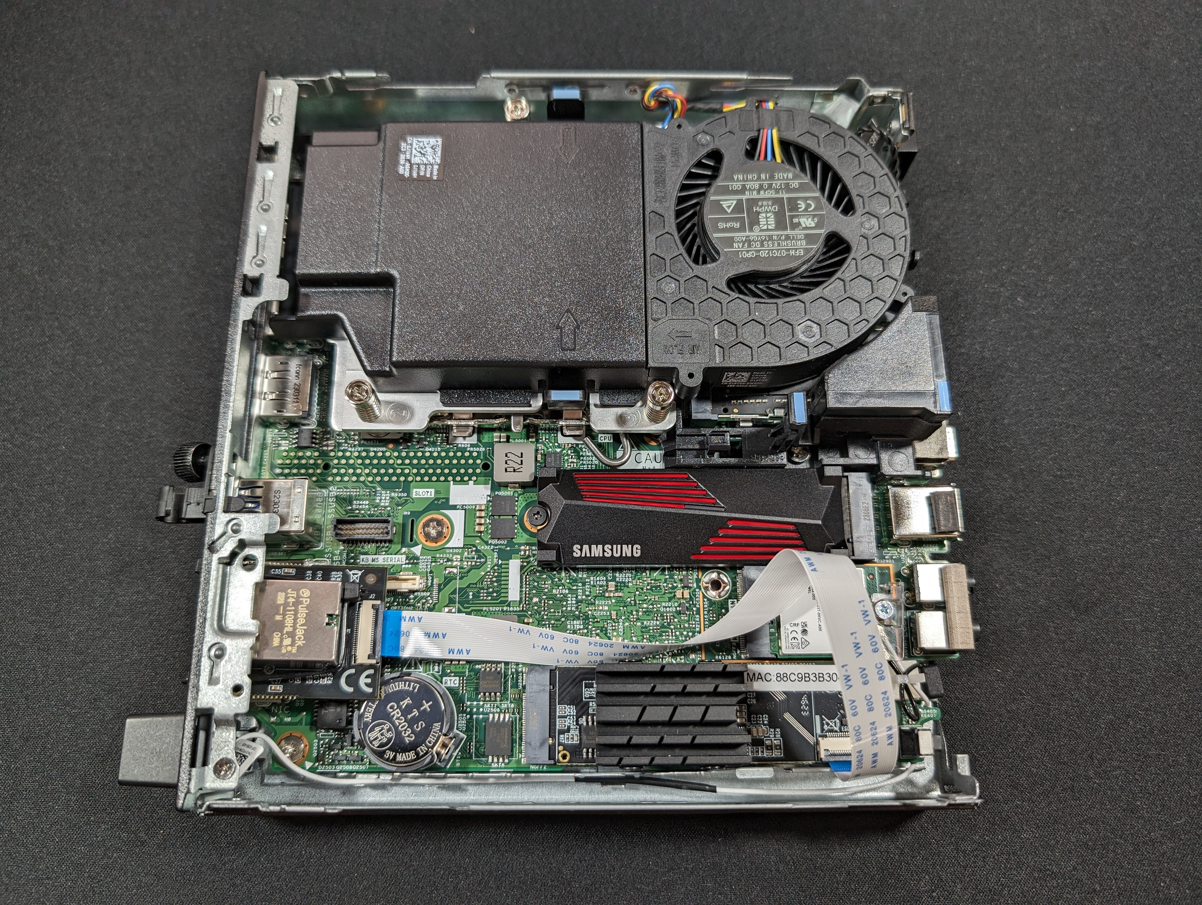
Dell 7010 Plus is a computers with 13th gen Intel processor that comes in a very small form factor and are quite easy to work on, with a max of 64GB of DDR5 RAM (possibly 128GB, but 64GB SO-DIMM sticks are unobtainable by me) and two M.2 slots.
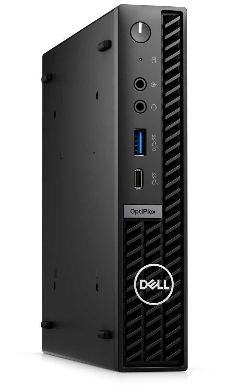
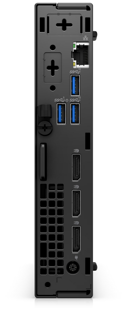
As you can see, there is 1x Gigabit Ethernet, 4x USB 3.1, 1 USB-C, 3 Display Port. The 10 Gigabit adapter will be punched through the expansion port with a permanently removable metal shield, left of the built-in Ethernet port in the second picture.
This won't work on all micro computers due to needing an M.2 slot and room for the heat sink (it needs the heat sink badly). For example, this won't work on a Lenovo Tiny.
How-to
Tools and Materials Needed
These are not affiliate links, I make no money with these recommendations.
- 1 x Dell 7010 Micro (I purchased 64GB RAM, 2TB SSD - $1,099.99 as of November 2023)
- 1 x Philips head #2 screwdriver ($5)
- 3 x 4" or 6" zip ties ($7 for a pack)
- 1 x SSD mounting screw ($6.99 for a pack)
- 1 x IO Crest 10 Gigabit M.2 M Key Ethernet Network Expansion Card ($85 as of December 2023)
- 1 x Ethernet cable ($1)
- 1 x Scissors ($8)
- 1 pack of PCI-E M.2 mounting screws
Total cost: $1,220, $120 for just the card plus materials
Step 1 - Prepare the 10Gb card
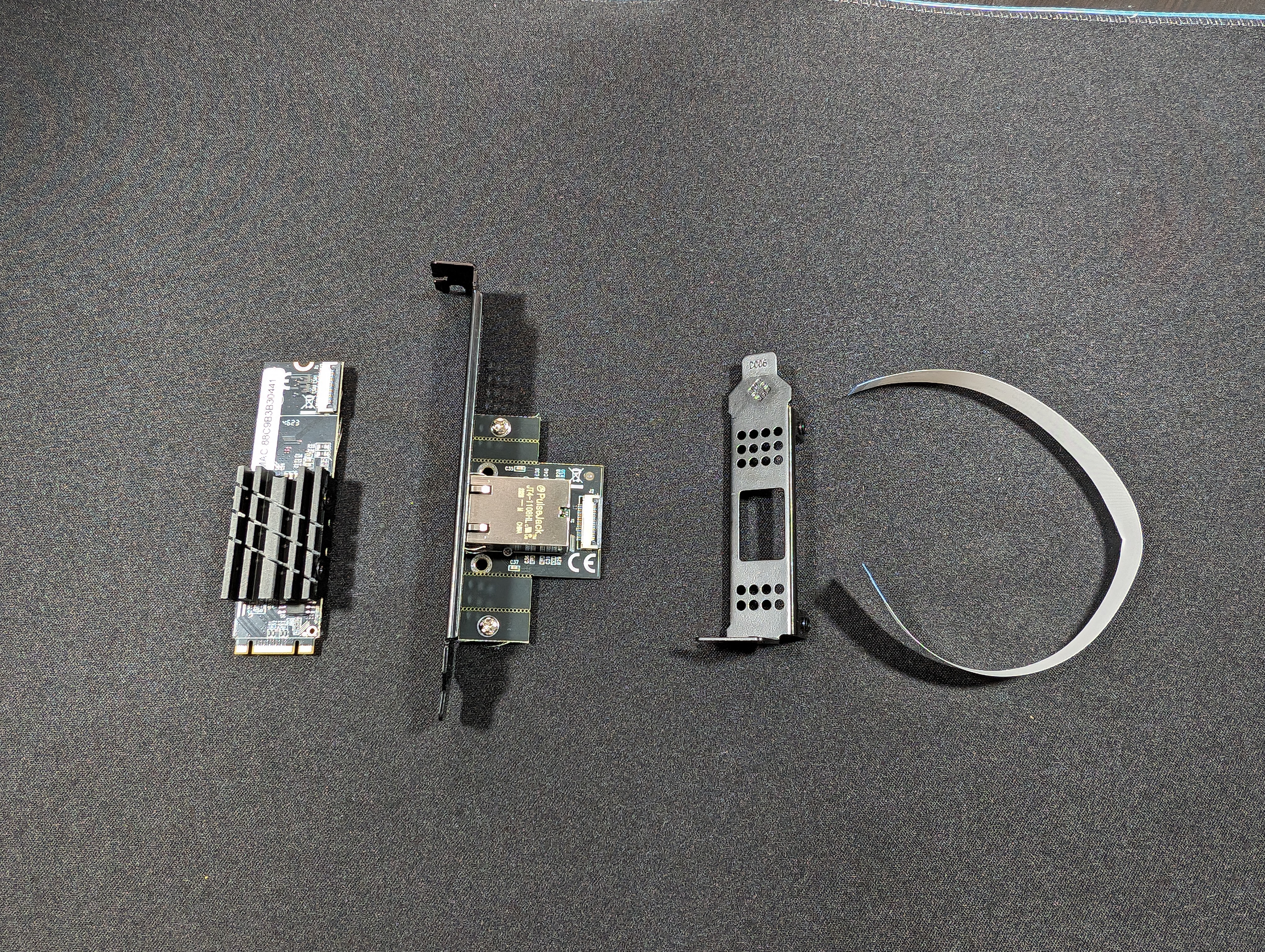
Your card will have an M.2 PCIe card, a ribbon cable (the alternate model has a cylindrical cable), a small PCB with an RJ45 shroud on it that's attached to a standard ATX size expansion slot cover.
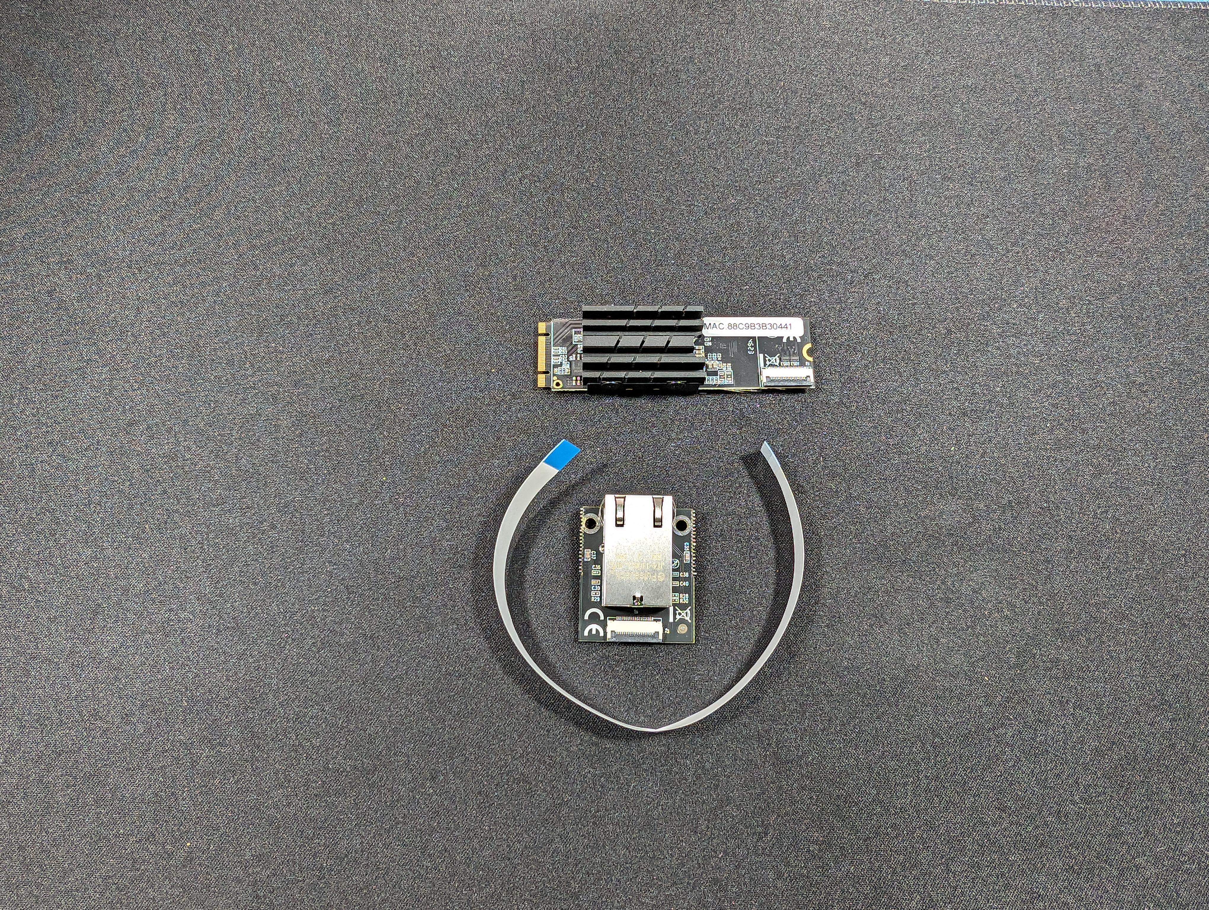
Remove the screws from the smaller board and break off both sections on both sides. If you have the older version, break off just outside the inner screw holes.
Step 2 - Permanently remove the shield on the Dell 7010 Plus Micro
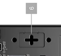
The Dell 7010 Plus Micro will come with a metal plate covering the COM port, use a Phillips head screwdriver to poke into the shield and wiggle it to remove it and create an opening for the RJ45 connector. It's the piece with the cross in the middle here.
Step 3 - Install the M.2 card
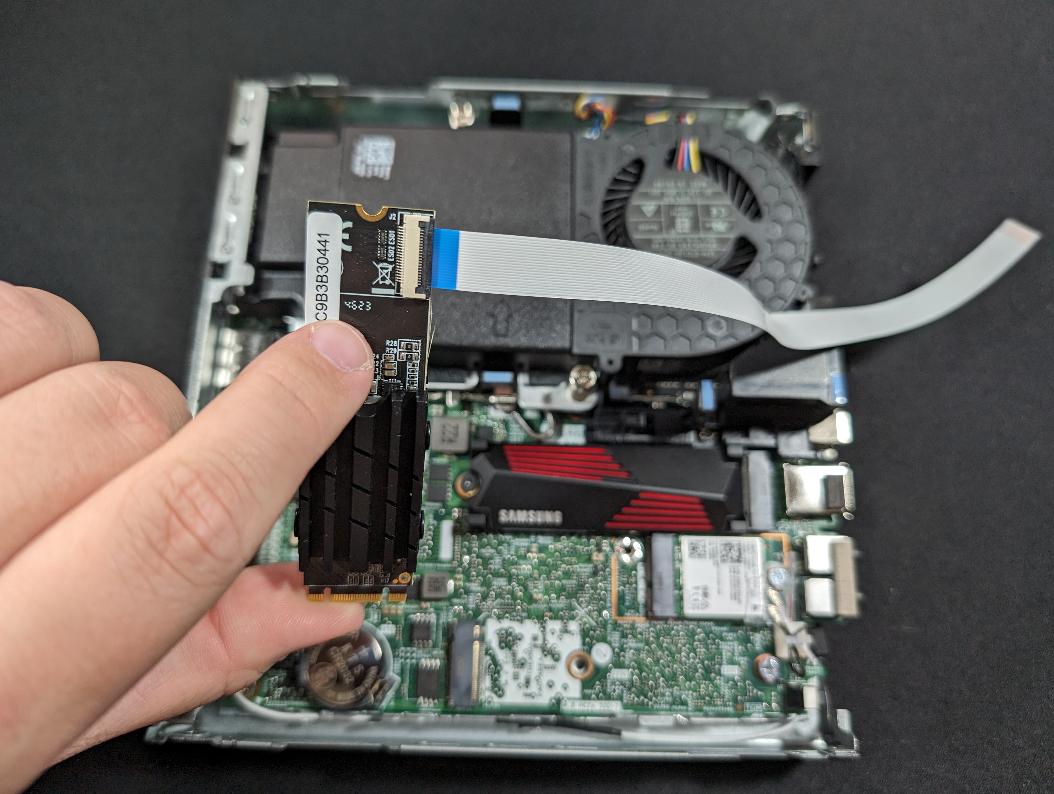
Attach the ribbon cable to the card (blue part up so the metal contacts on the other side make contact with the ones on the card). Clamp down the black part (it rotates on a hinge).
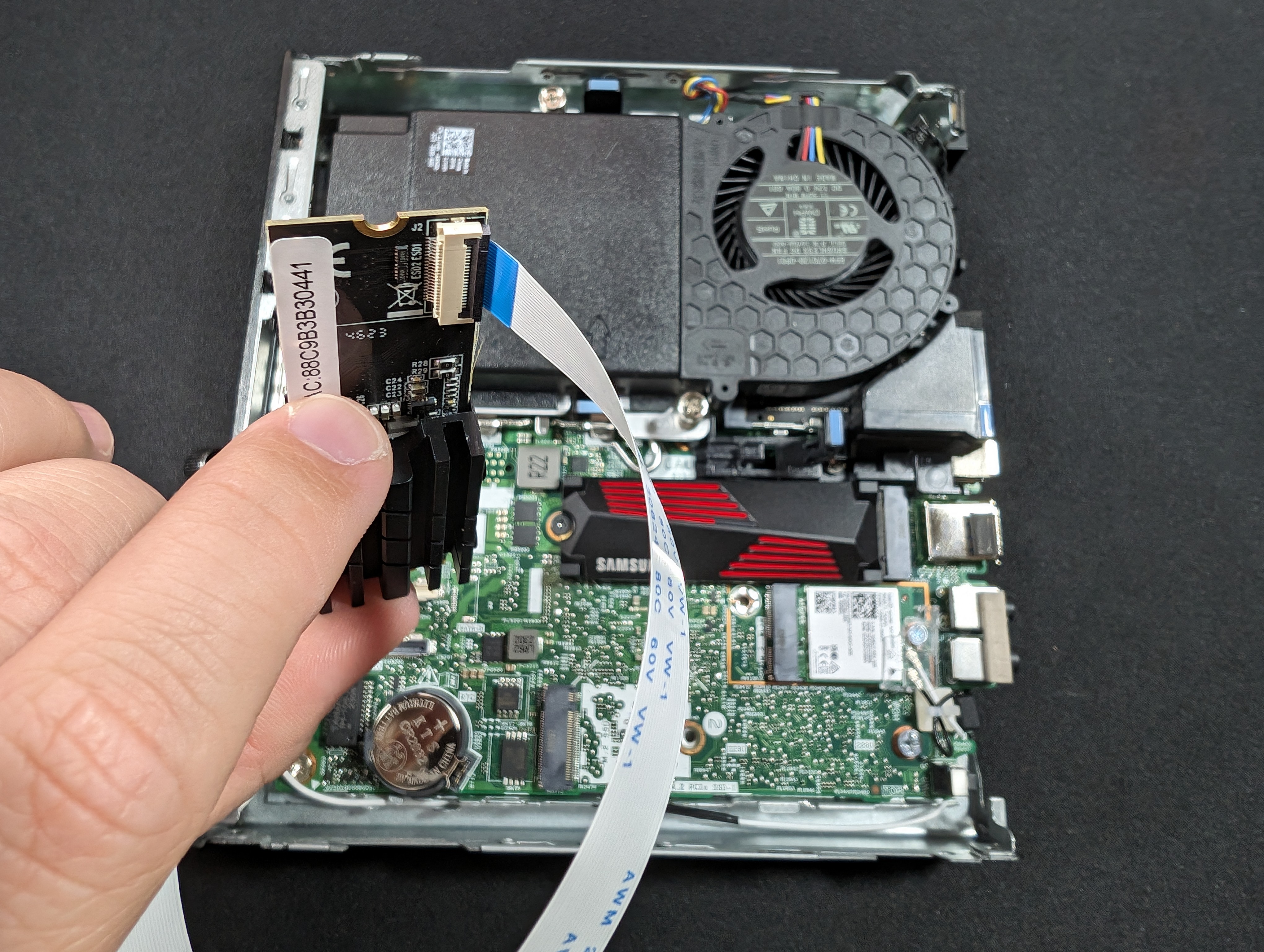
GENTLY and SLOWLY bend the ribbon cable upwards (you don't need to get a 90° angle, in fact that's not recommended), but enough so that the card fits easily in the M.2 slot without any stress on the ribbon cable connector on the card.
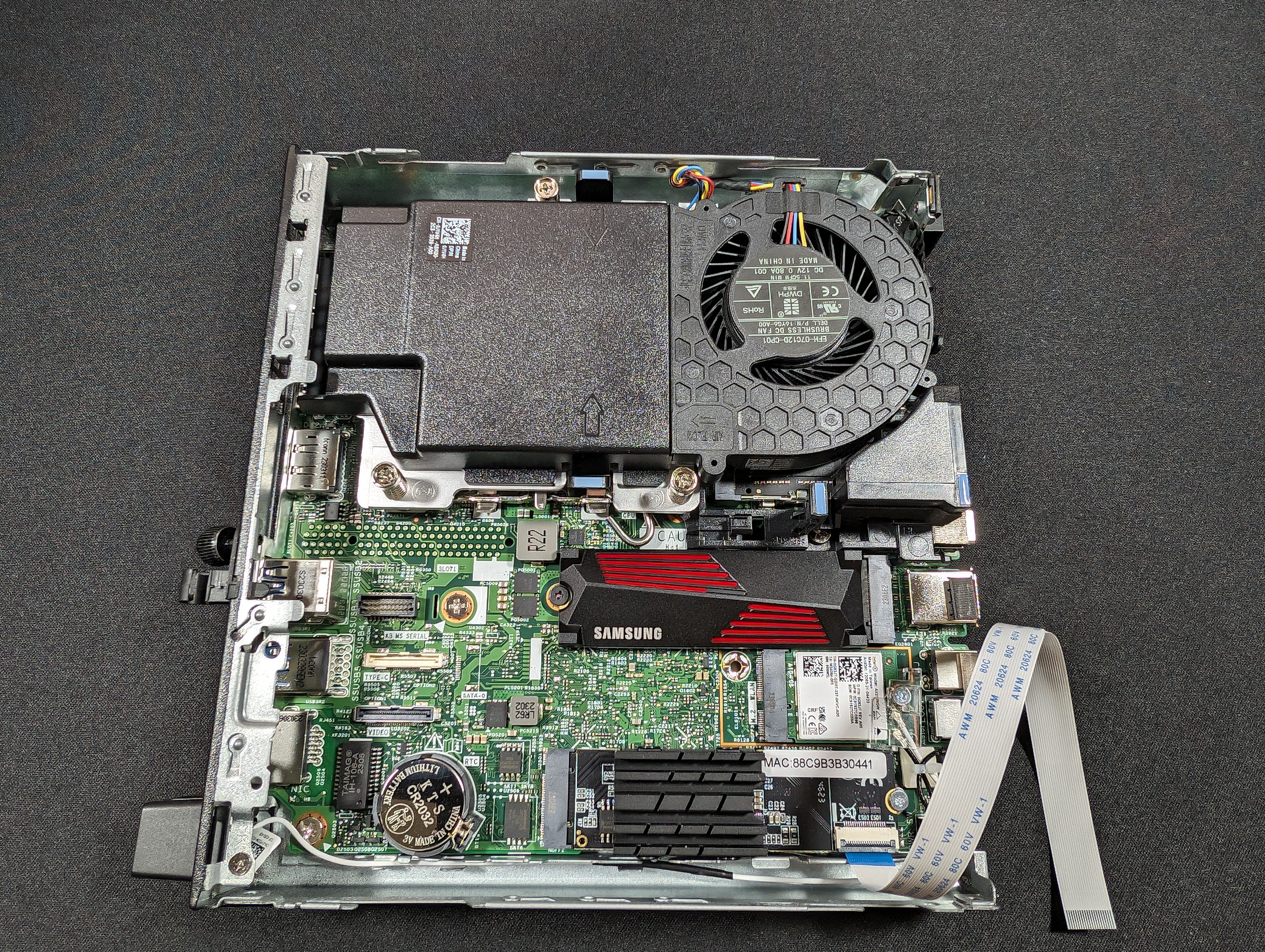
Install the M.2 card into the slot and secure it using an M.2 screw, which can be screwed directly onto the existing screw on the motherboard. This acts as a spacer as well as an anchor point.
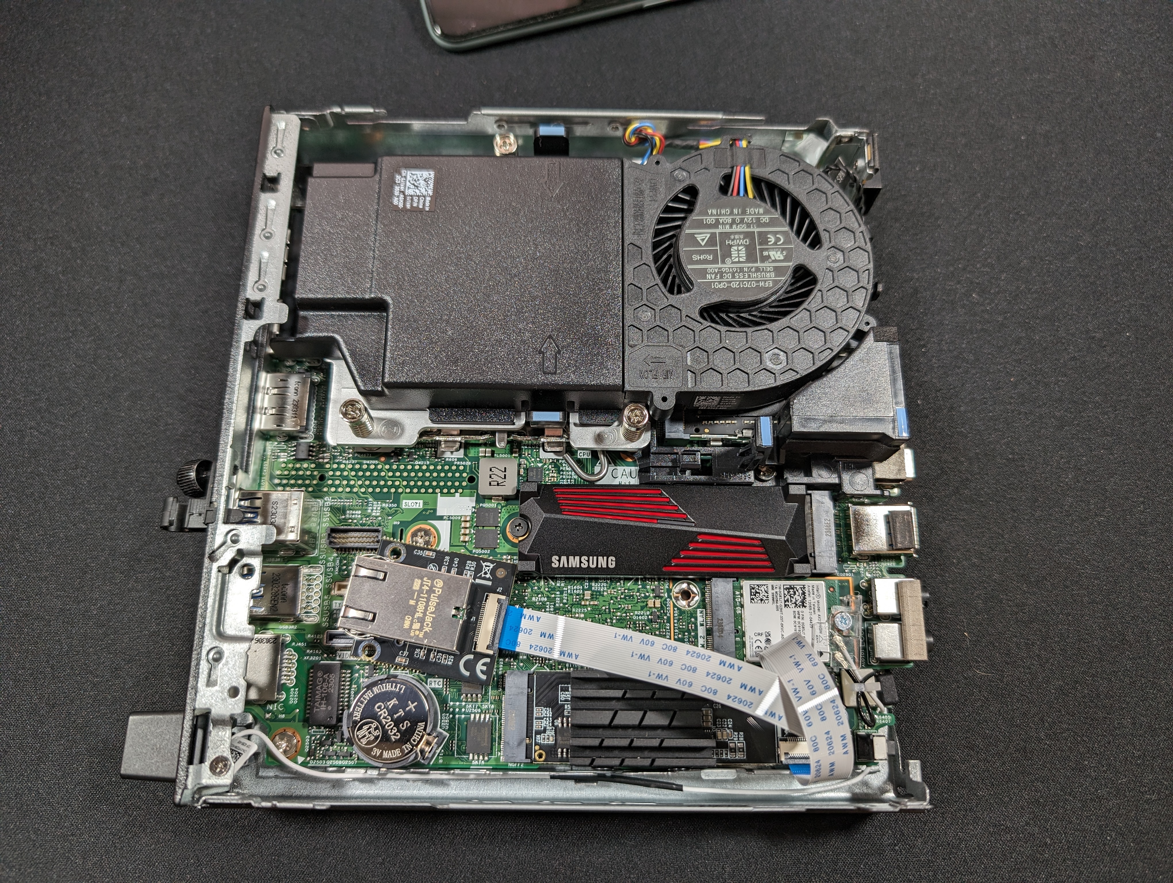
Attach the other end of the ribbon cable to the PCB with the Ethernet port on it. Turn it 360° counter(anti)clockwise so there's a small loop in the cable. This encourages the cable not to be close to the heatsink or the other M.2 slot which will probably have an SSD that gets warm too.
Step 4 - Set up the zip tie attachment arrangement
Step 4.1
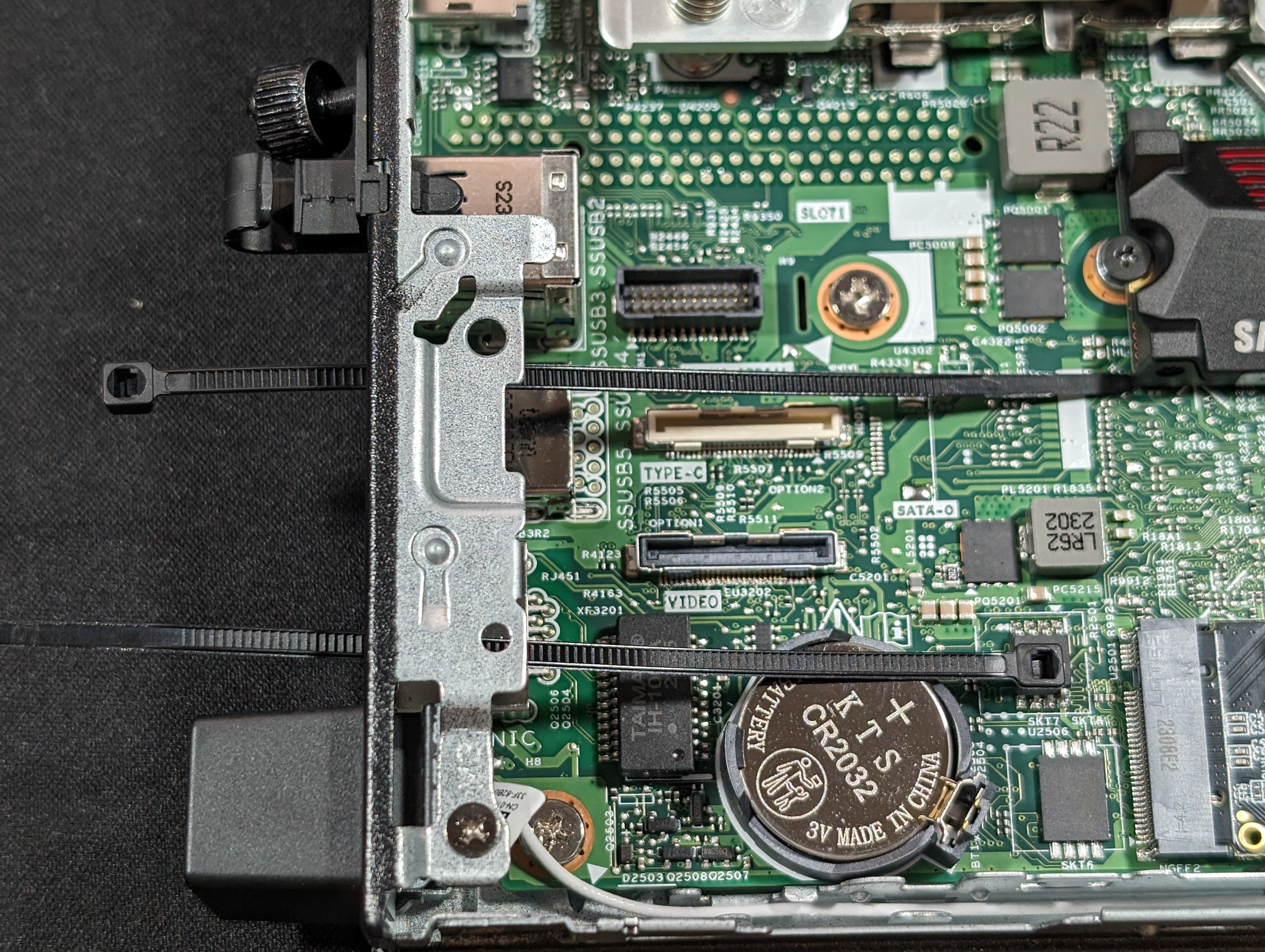
Place the zip ties through the holes on the sides of COM port going opposite ways.
Step 4.2
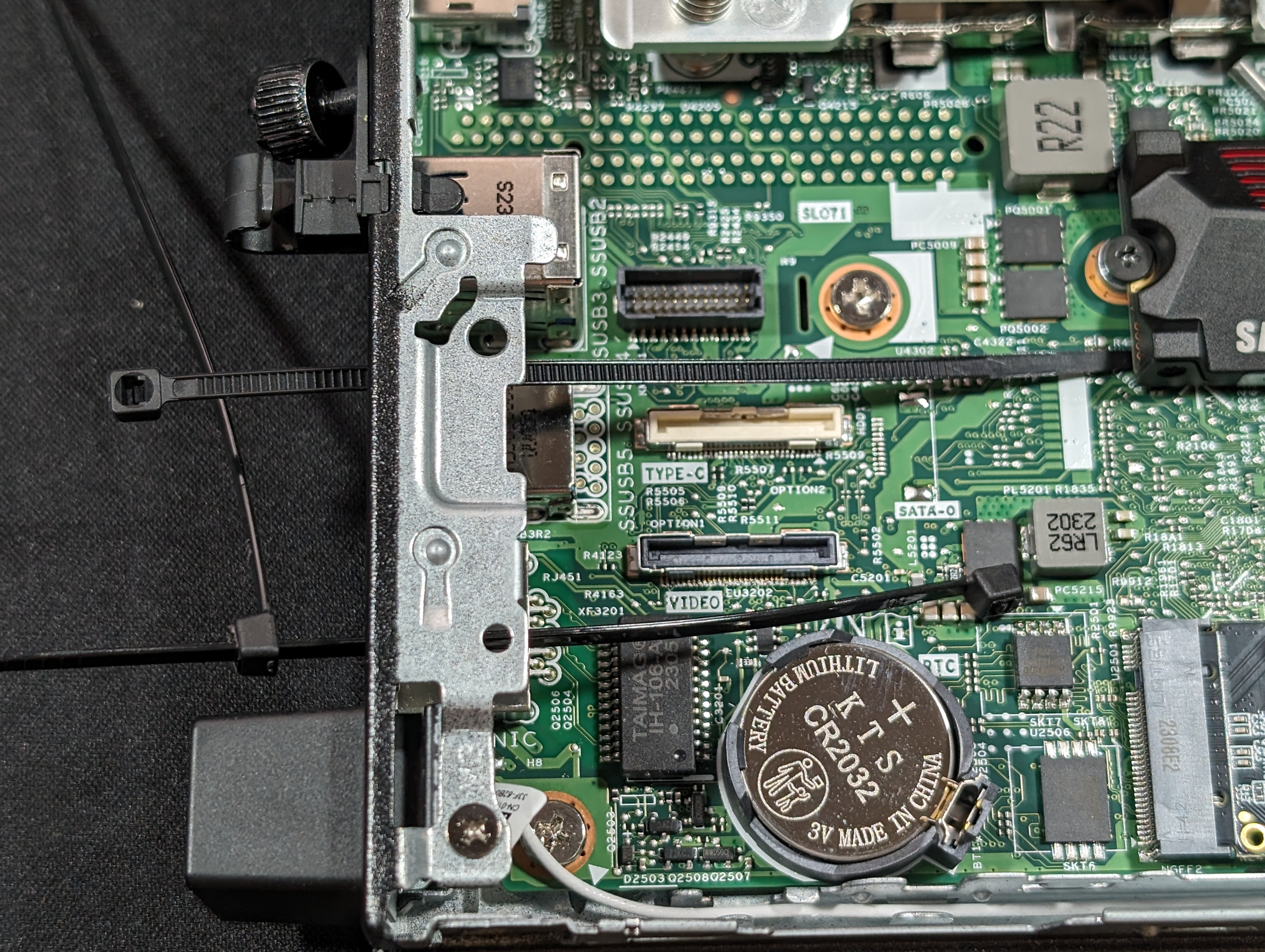
On the side with the thin end protruding from the system, attach another zip tie and slide it until it clicks, but only a few times.
Step 4.3
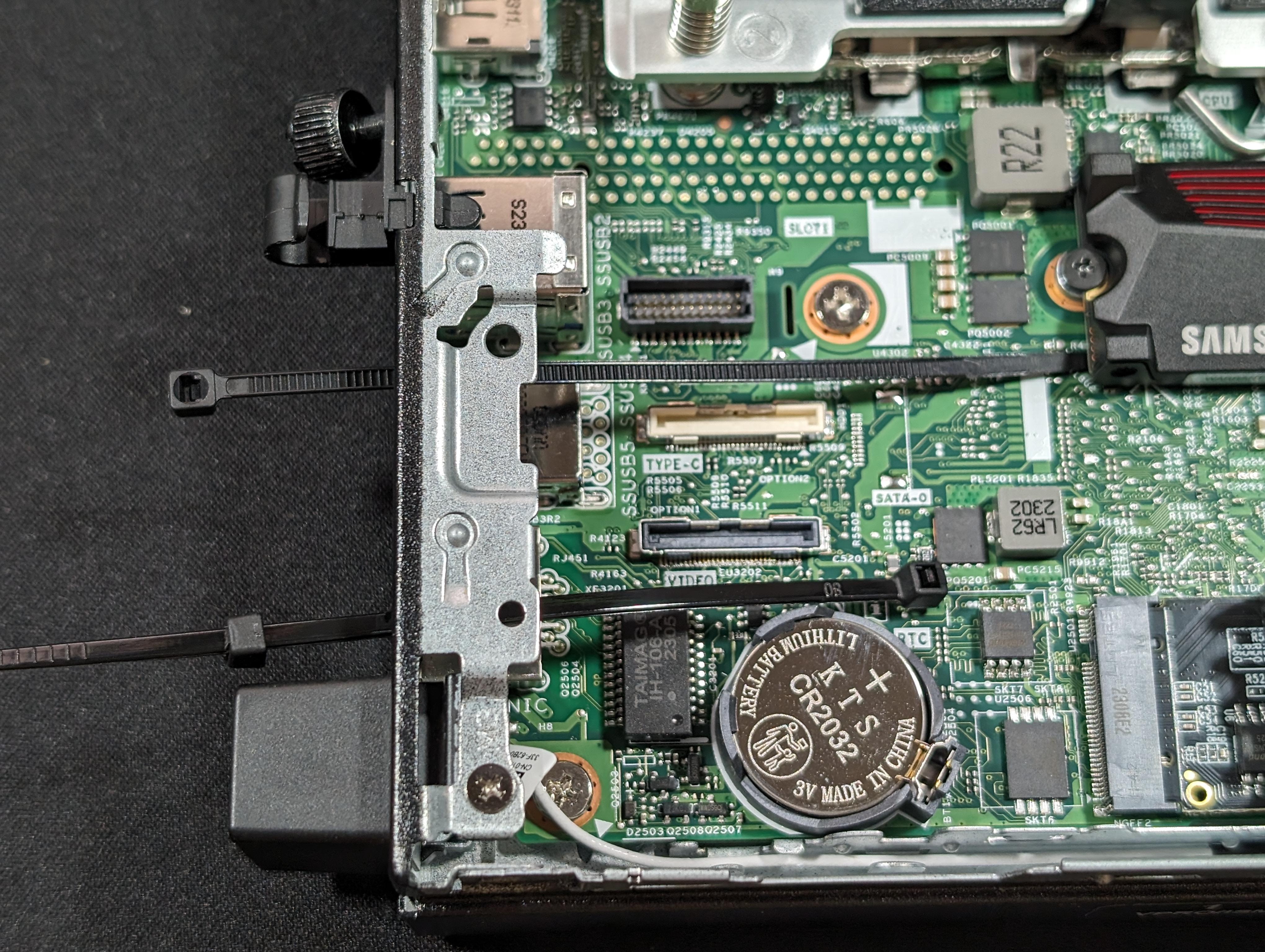
Clip the extra plastic off the zip tie you just added, effectively adding a square zip tie "cap" to the end of the zip tie
Step 4.4
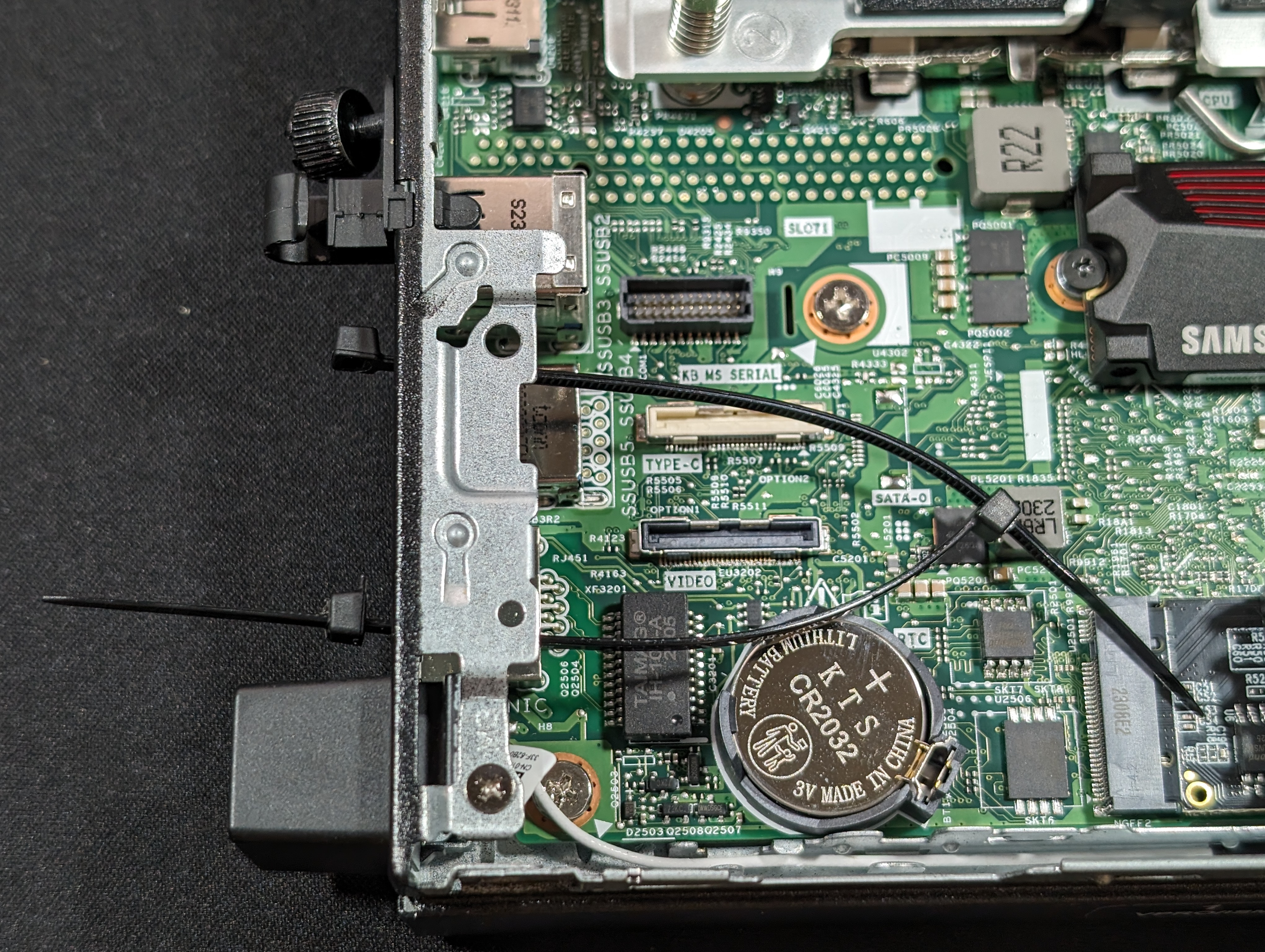
On the inside of the system, slide the zip ties together, but only for a few clicks.
Step 5
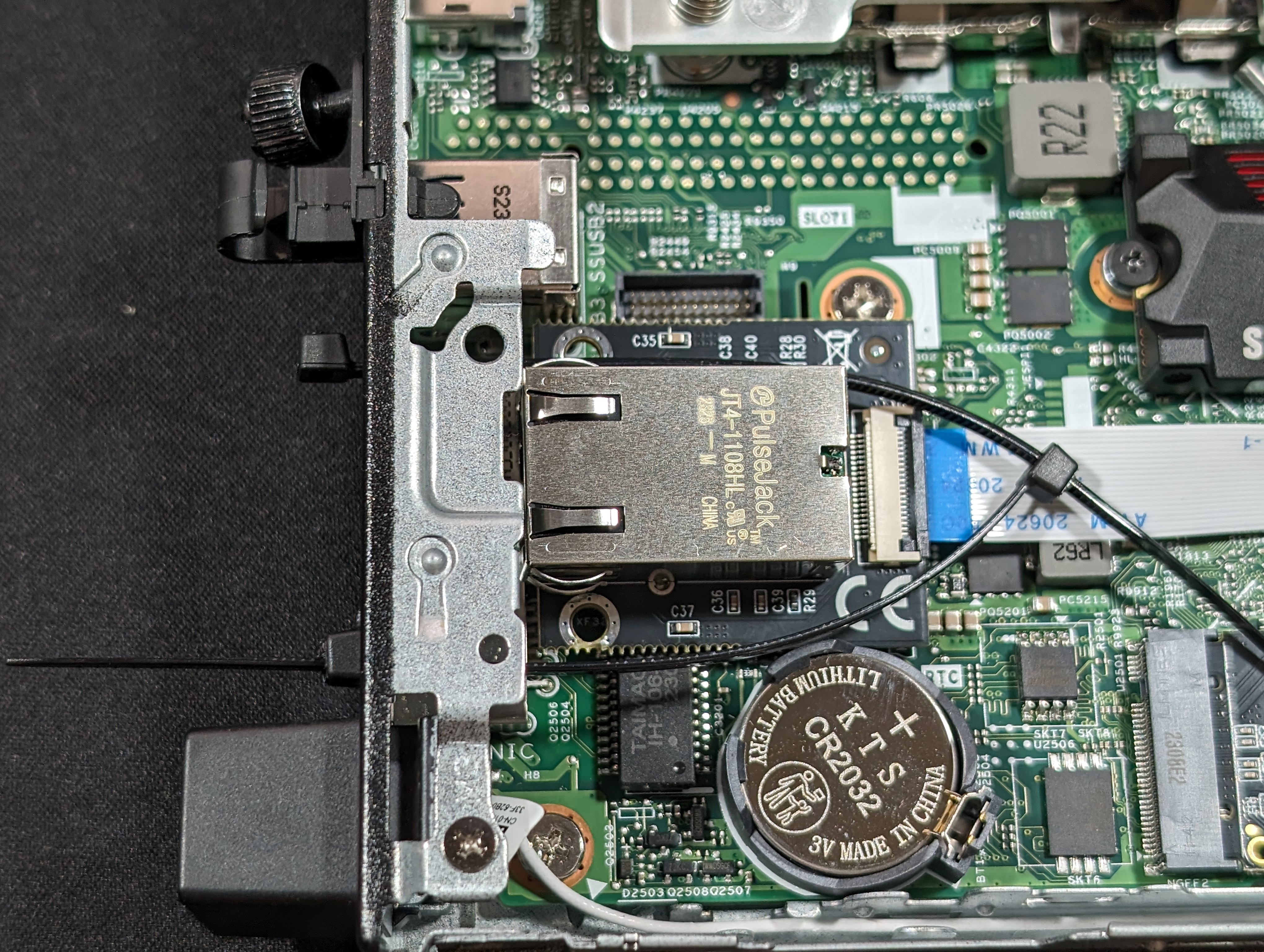
Place the small PCB inside into the zip ties so that they encircle the RJ45 port shroud.
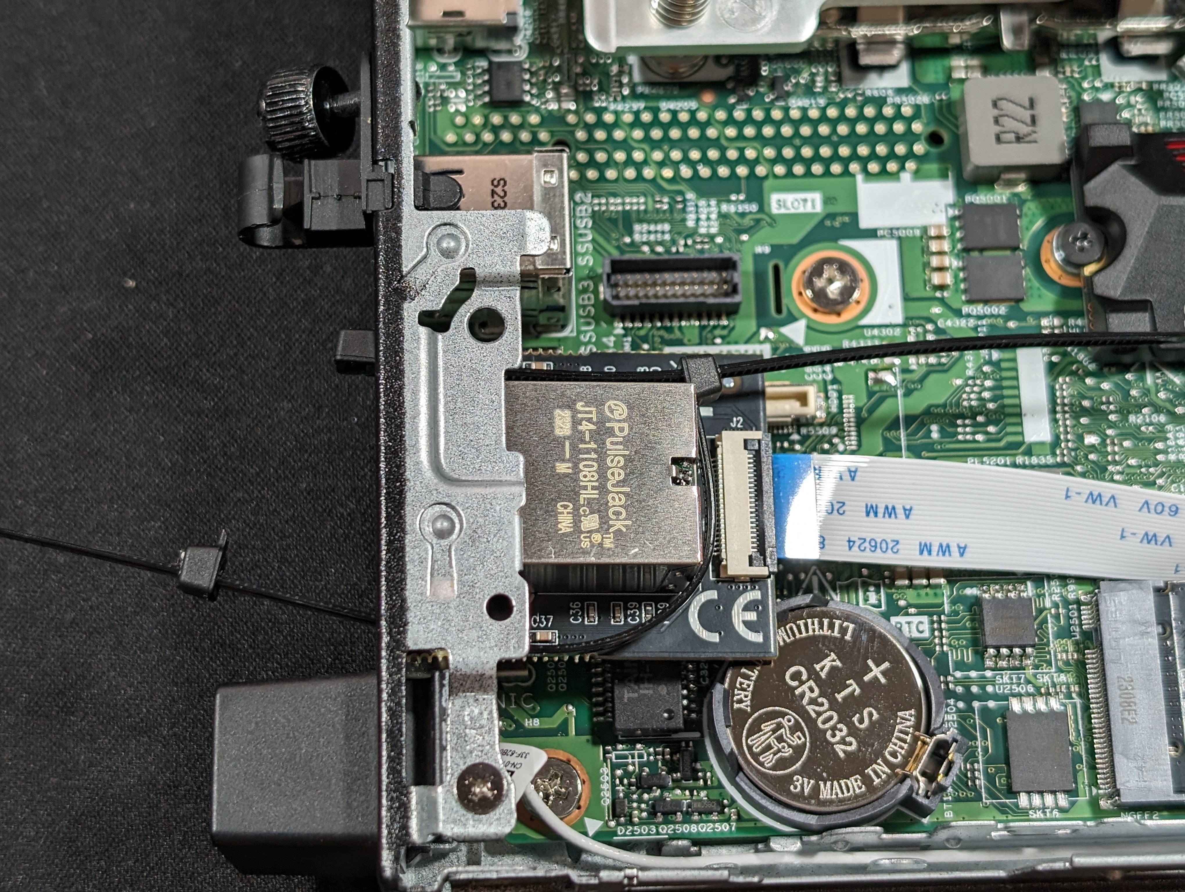
Zip one end so that there's a 90 degree angle against the inside corner of the RJ45 port shroud.
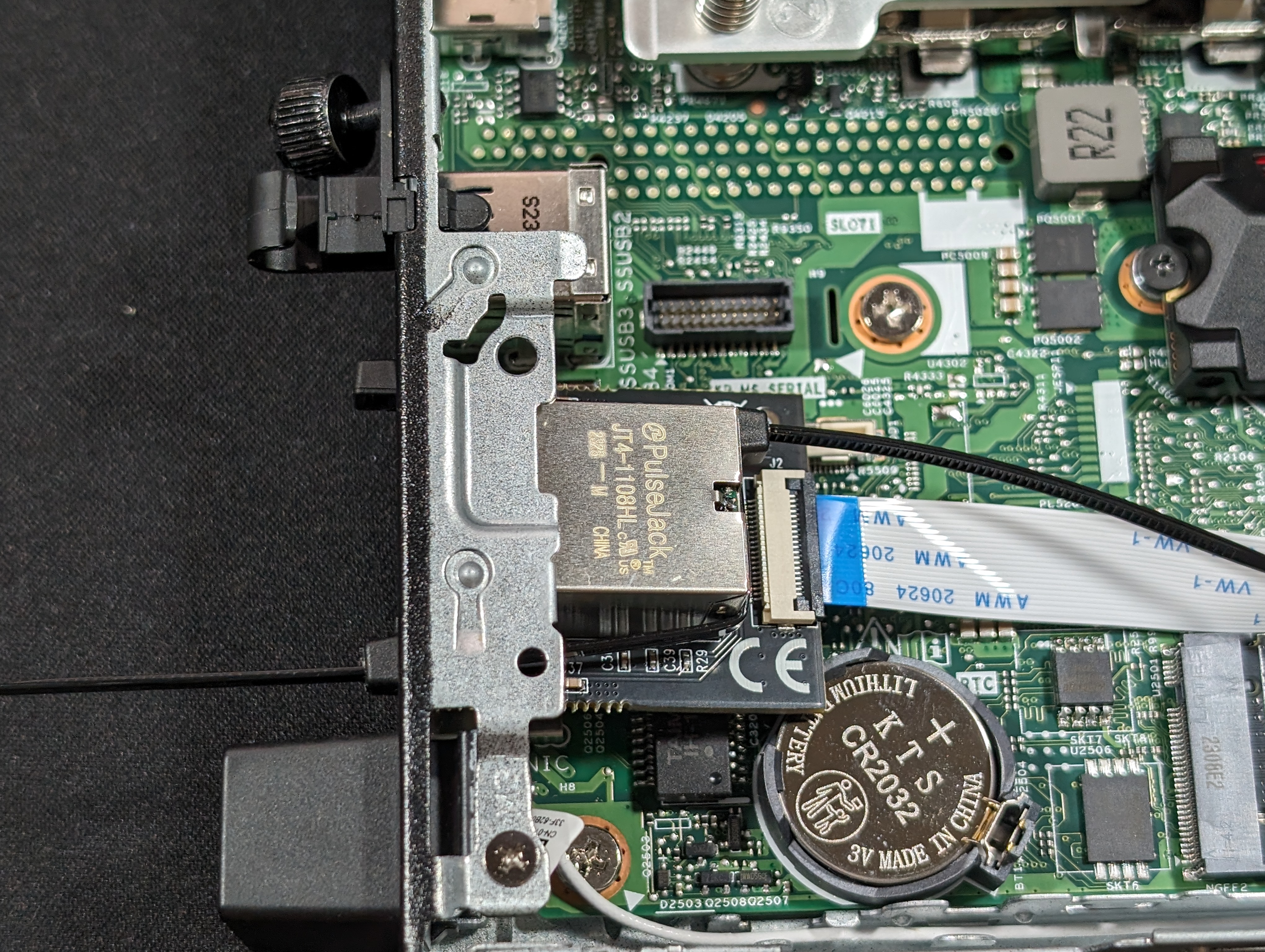
Fully tighten the zip tie on the other side
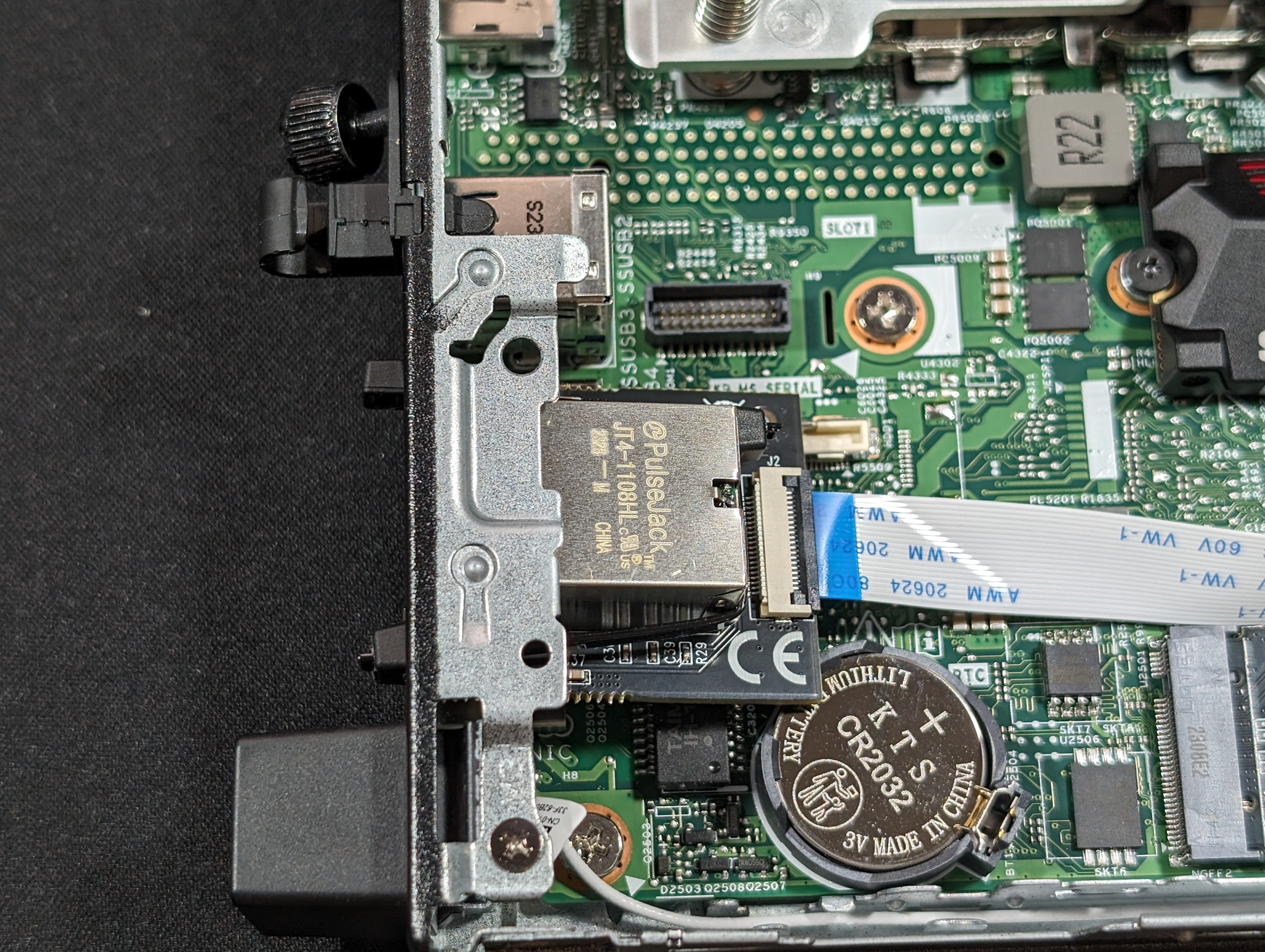
Clip off the extra (you don't need to clip the free ends too short, just enough to it's out of the way)
Step 6

Route the ribbon cable around so that it generally stays away from the heat sink or the SSD.
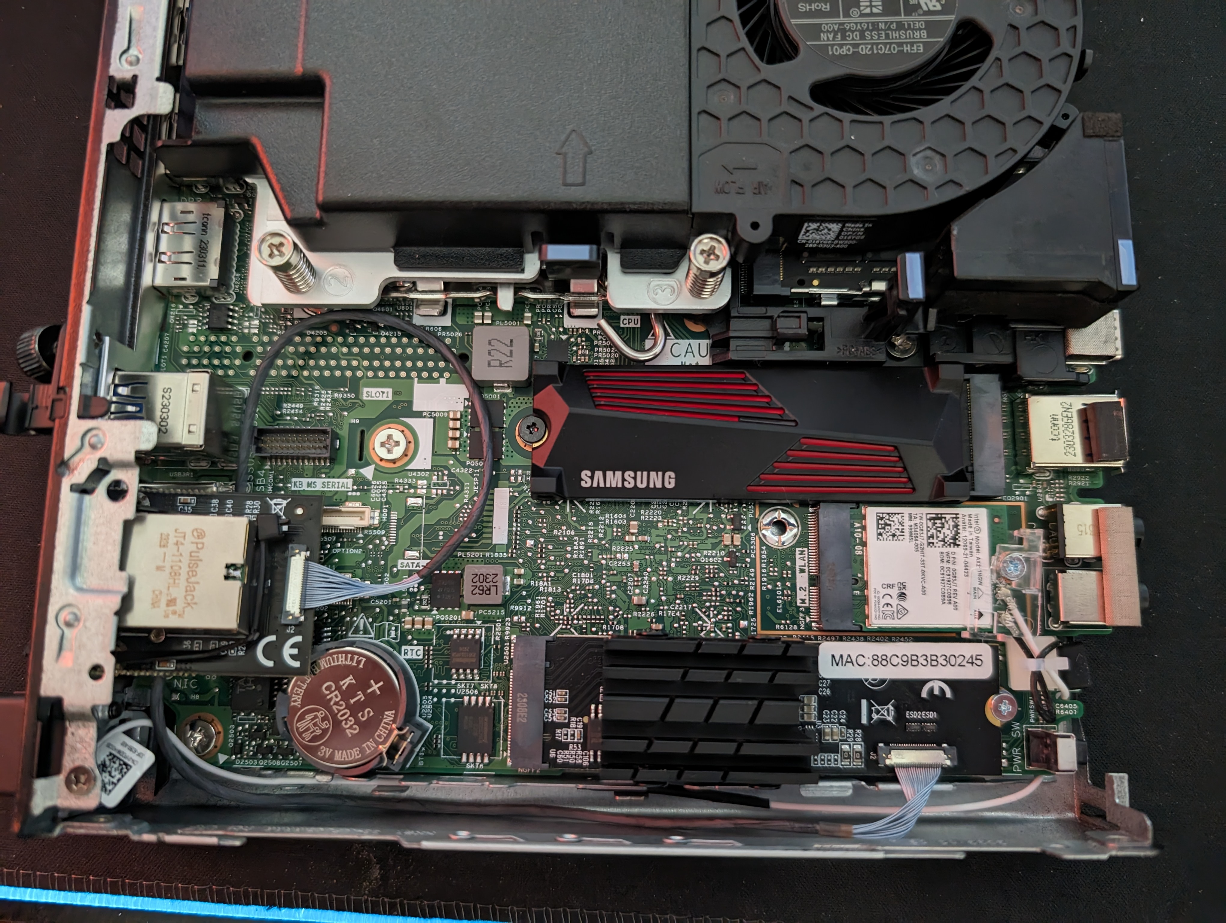
If you have the variant with a cylindrical cable, I recommend mostly following the existing WiFI/Bluetooth antenna if you have it, as shown.
Step 7
Re-assemble the system.
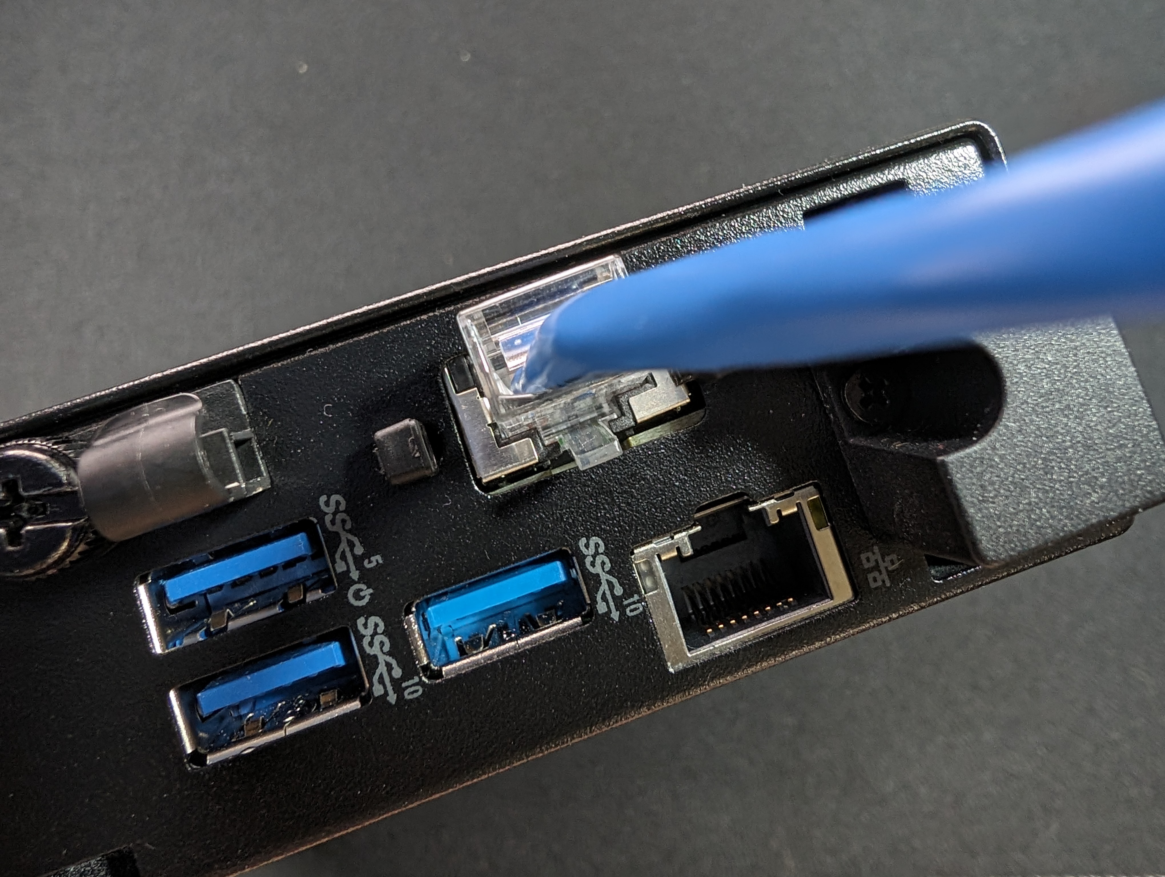
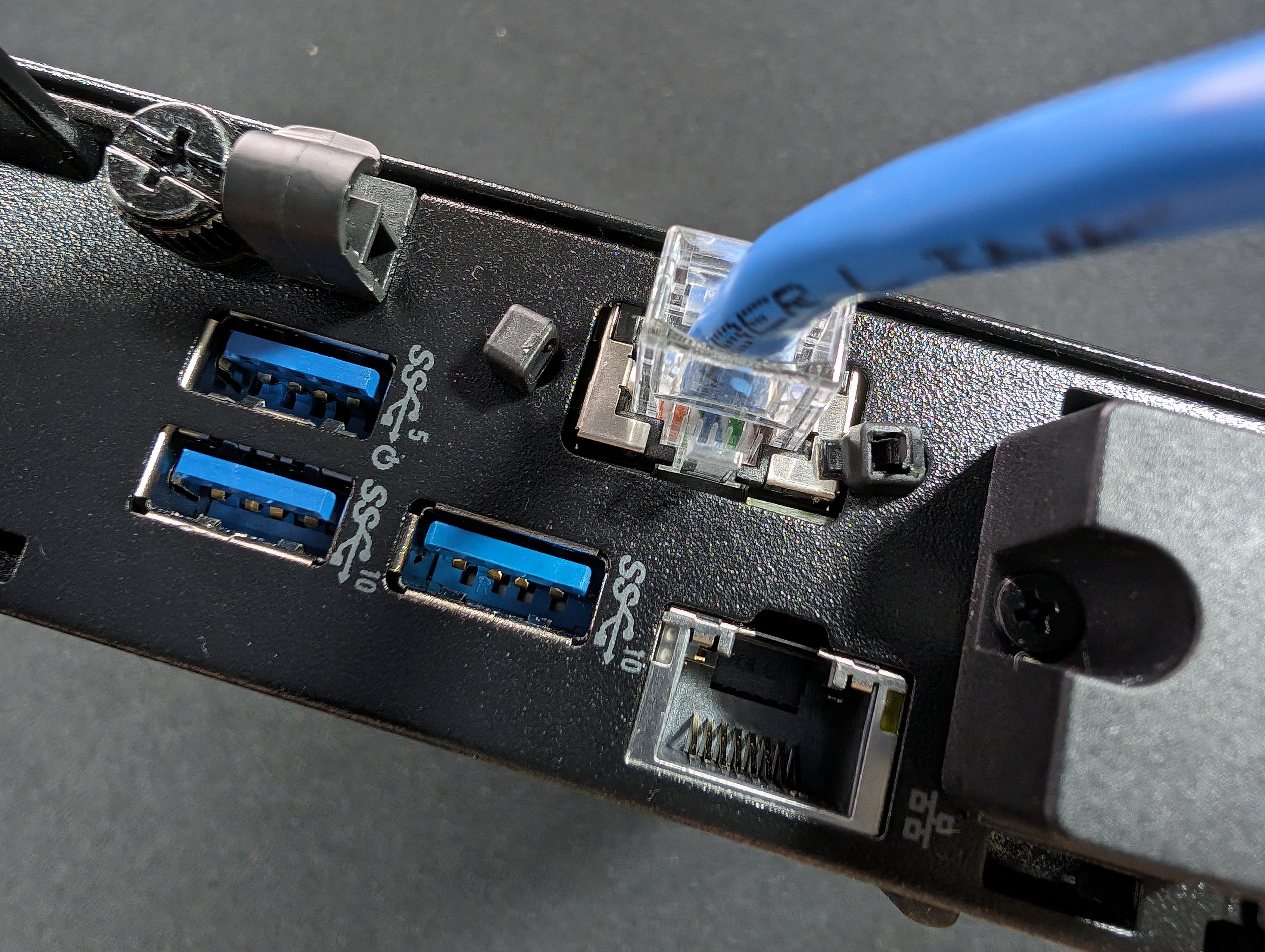
Use an ethernet cable to adjust the port if necessary. It should be easy to plug one in but if you want to straighten it up, you can use the cable to move the port around. Zip-tie engineering has its limits, so there will almost definitely be some play no matter what you do.
Step 8
As far as drivers go, the chipset/linux-firmware driver this uses is atlantic.
03:00.0 Ethernet controller: Aquantia Corp. AQC107 NBase-T/IEEE 802.3bz Ethernet Controller [AQtion] (rev 02)
    Subsystem: Aquantia Corp. AQC107 NBase-T/IEEE 802.3bz Ethernet Controller [AQtion]
    Kernel driver in use: atlantic
    Kernel modules: atlantic
Step 9
Add this to your kernel boot parameters:
pcie_aspm=off
You can also forcefully disable this in the BIOS.
