Adding 2.5G Ethernet to Dell 7040 (and other similar micro computers)
Information and Background
With many thanks to Perihelion in the k8s@home Discord.
(Skip to the "How-to" section if you're already familiar with these computers)
Dell 7040s are computers with 6th gen Intel processors that come in a very small form factor and are quite easy to work on, with a max of 64GB of RAM, an M.2 slot as well as a 2.5" SATA port. They are quite powerful and refurbished units can be found cheaply online. If you buy a refurbished unit, check the TBW of the solid state or replace it ahead of time because they will be of wildly varying quality and often from unfamiliar or lower-quality manufacturers.
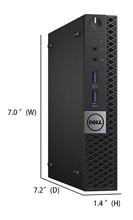
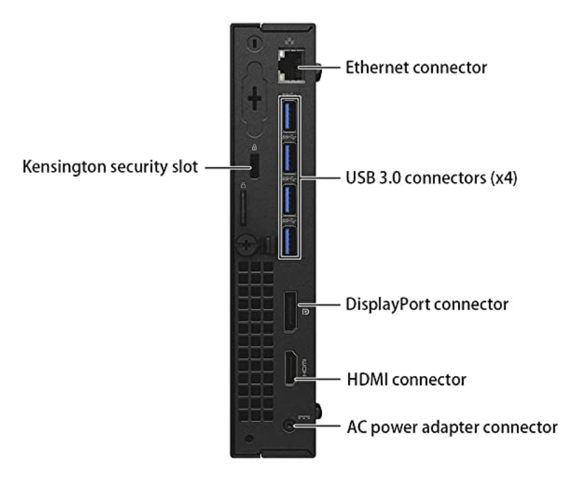
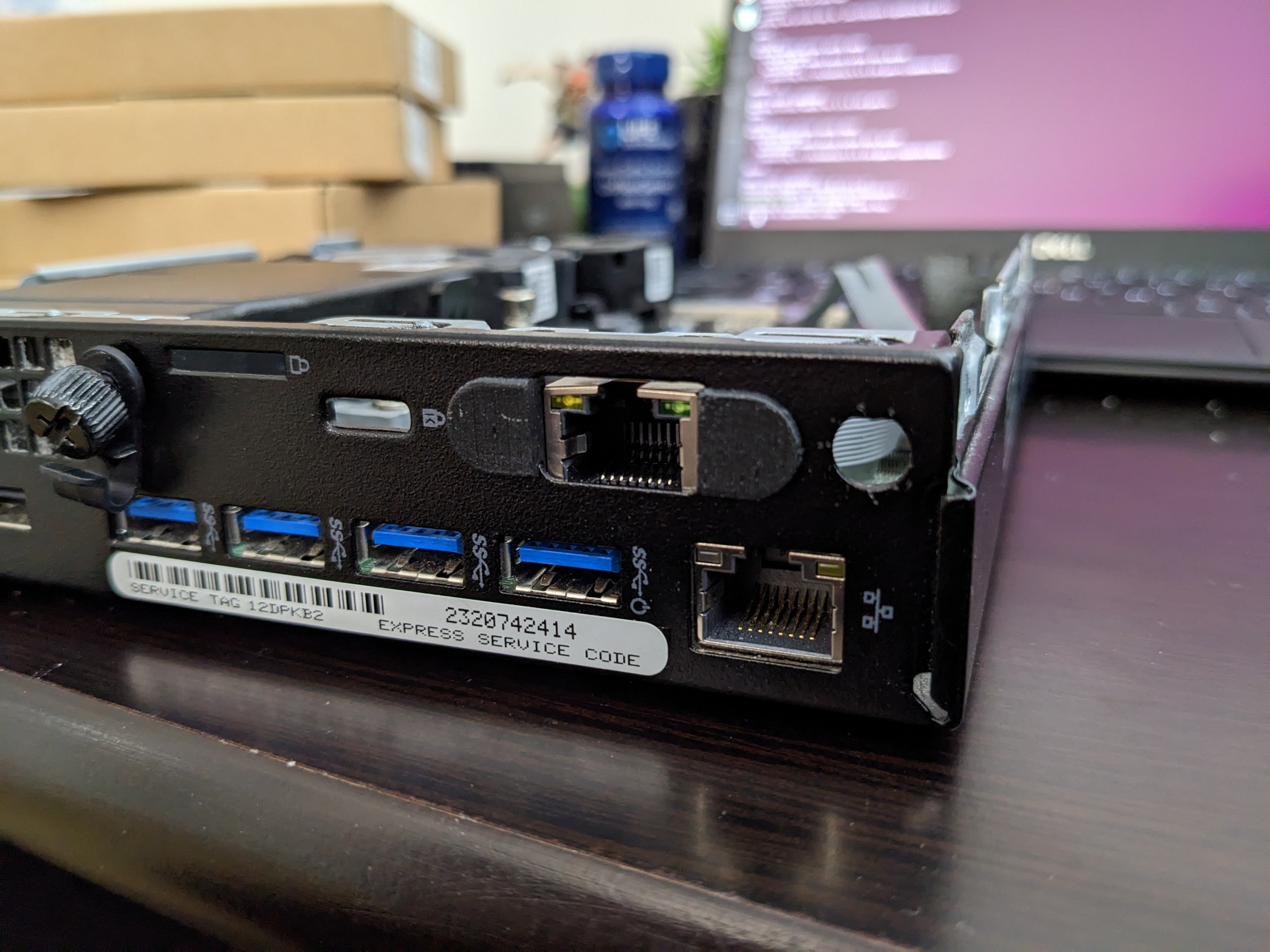
As you can see, there is 1x Gigabit Ethernet, 4x USB 3.1, Display Port and HDMI. The 2.5 Gigabit adapter will be punched through where the serial or VGA ports often are, above the Kensington security lock in the picture (a removable shield is in that spot in the picture).

This is an in-progress picture showing the 2.5 Gigabit ethernet port and some mounting pieces that help secure the port.
How-to
Tools and Materials Needed
- 1 x Dell 7040 or a similarly sized computer with a Mini A+E PCI-E slot, which is popular for WiFi cards (can be found refurbished for $200-$300).
- 1 x Philips head #2 screwdriver ($5)
- 2 x 4" or 6" zip ties ($7 for a pack)
- 1 x A set of these mounting pieces (two pieces in each set) created by eriz.
- 3D print them yourself or commission someone to print them for you. I used TKAstudio. (I got 6 sets for about $15)
- 1 x M.2 A+E KEY 2.5G Ethernet LAN Card RTL8125B card ($15)
- 1 x Ethernet cable (it actually would be a good thing if you broke off the plastic retaining piece at the top) ($1)
- 1 x Scissors ($8)
Total cost: ~$239-$339
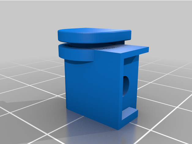
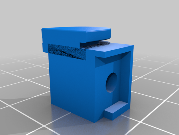
These are the pieces to print.
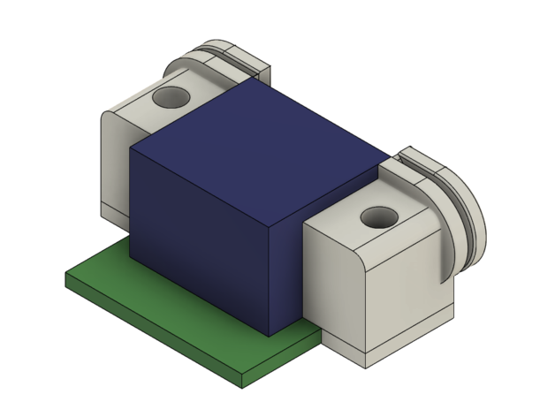
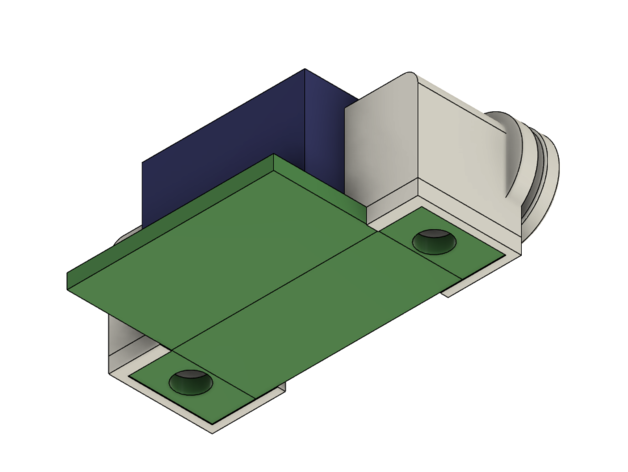
This is a rendering of how the pieces fit with the ethernet port.
Pre-installation
## Install 2.5G DKMS driver
sudo add-apt-repository -y ppa:awesometic/ppa
sudo apt install -y realtek-r8125-dkms
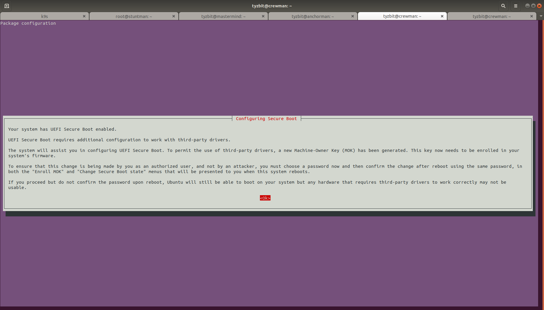
At this point, if you have secure boot enabled, first off: good for you! Second off, this means you'll have a little more configuration later on.
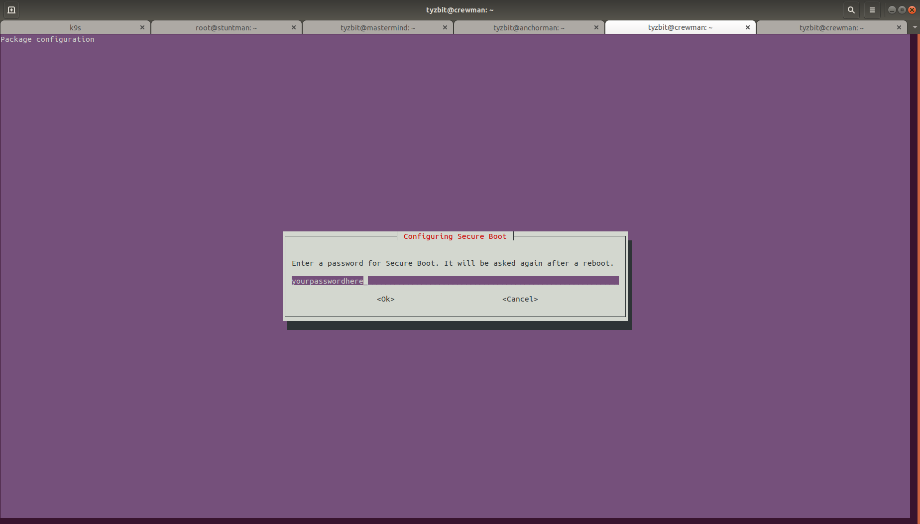
Pick a password (you will need it after you boot the system up, so DO NOT FORGET IT. It can be any password, so writing it down isn't a bad idea since you only need it once.)
## Blacklist underperforming Realtek module (it might get updated for better performance and if it does, you can remove this)
sudo tee -a /etc/modprobe.d/blacklist-r8169.conf > /dev/null <<EOT
# To use r8125 driver explicitly
blacklist r8169
EOT

## Remove poor-performing module to ensure the r8125 module is used.
sudo rmmod r8169
sudo update-initramfs -u
If you use netplan, you should also prepare your netplan config.
$ sudo vi /etc/netplan/00-installer-config.yaml
network:
  ethernets:
    enp3s0:
      dhcp4: true
      optional: true
  version: 2
You can shut the computer off now and proceed to installing the card.
You can also edit DHCP for your network at this point and enter in the MAC address (usually printed on a sticker attached the physical card itself) to ensure it comes up with the right IP the first time.
Step 1
You must install the necessary kernel module if you haven't already. Make sure you've completed the Pre-installation steps.
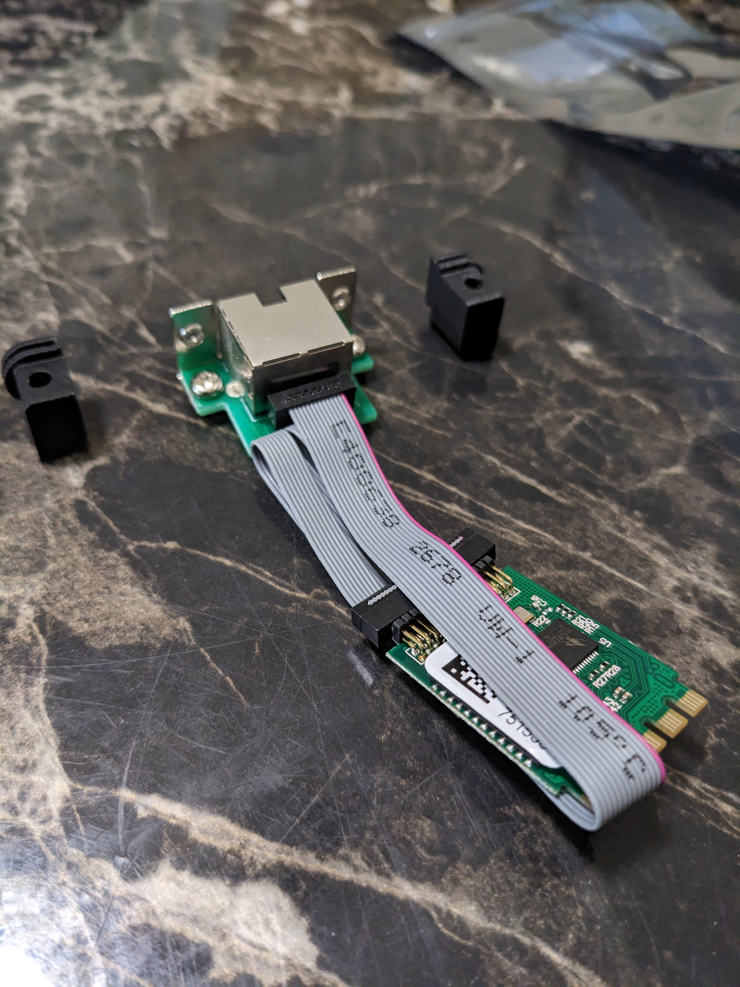
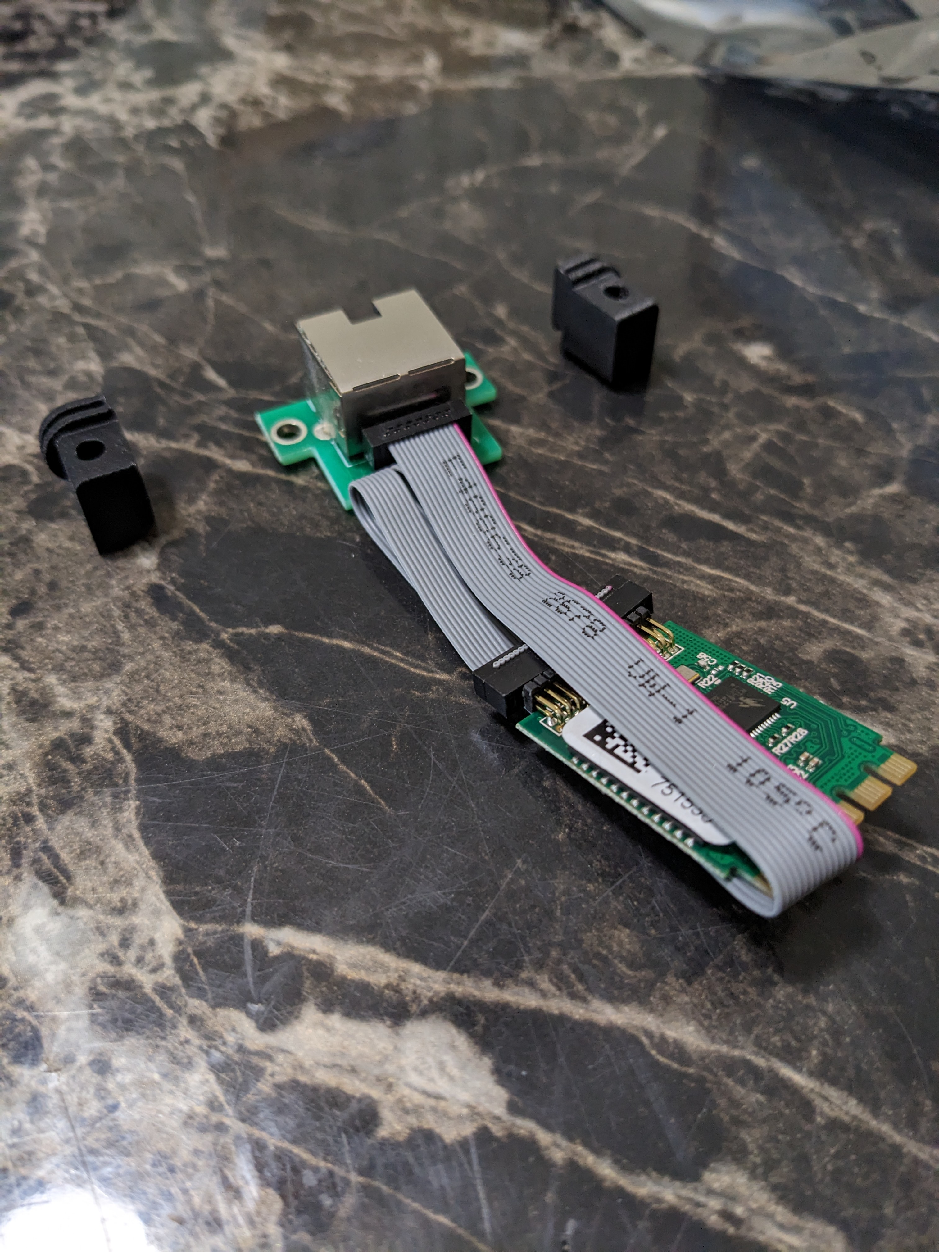
The card will come with a metal mounting shield, use a Phillips head screwdriver to remove the shield.
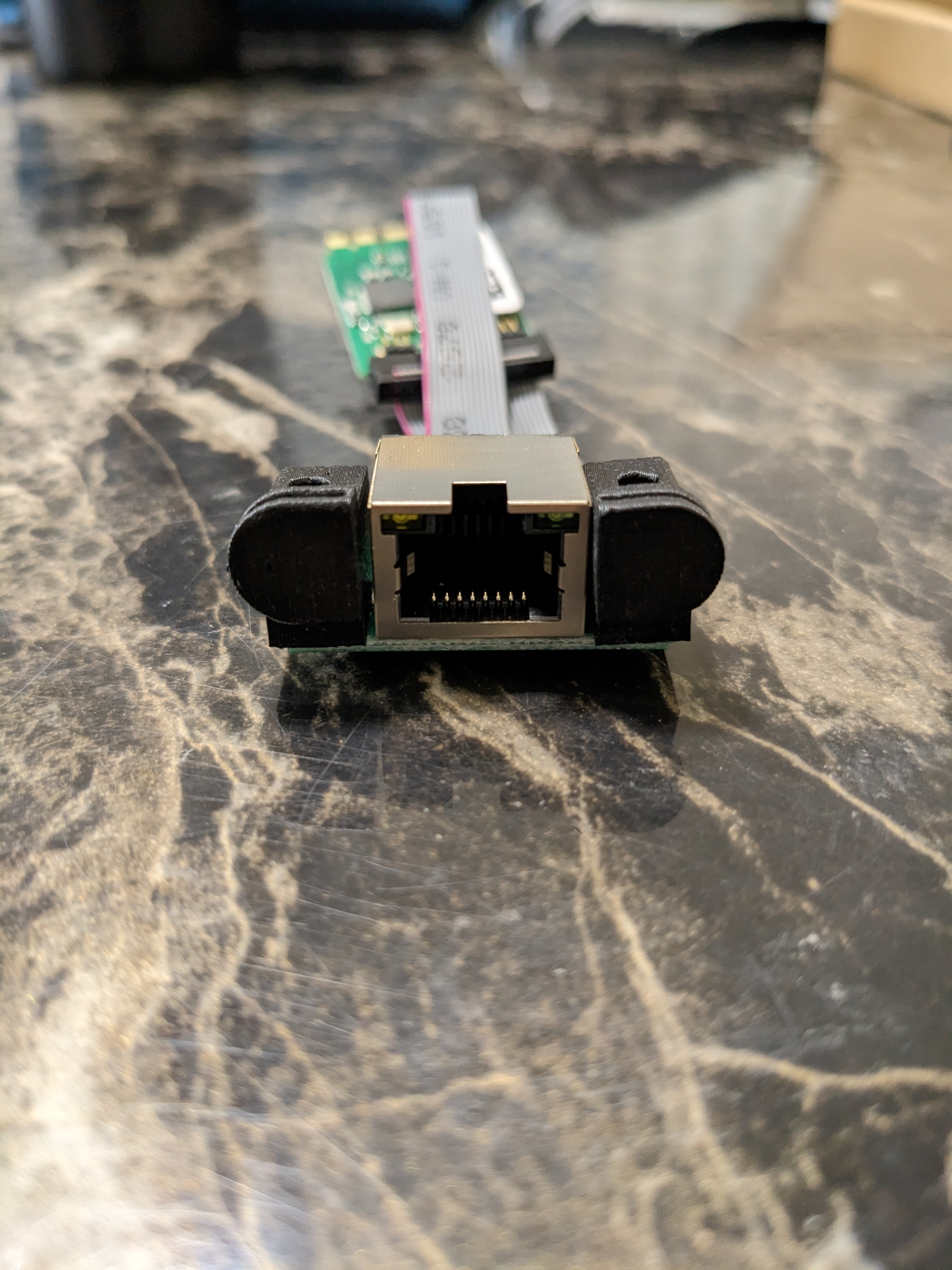
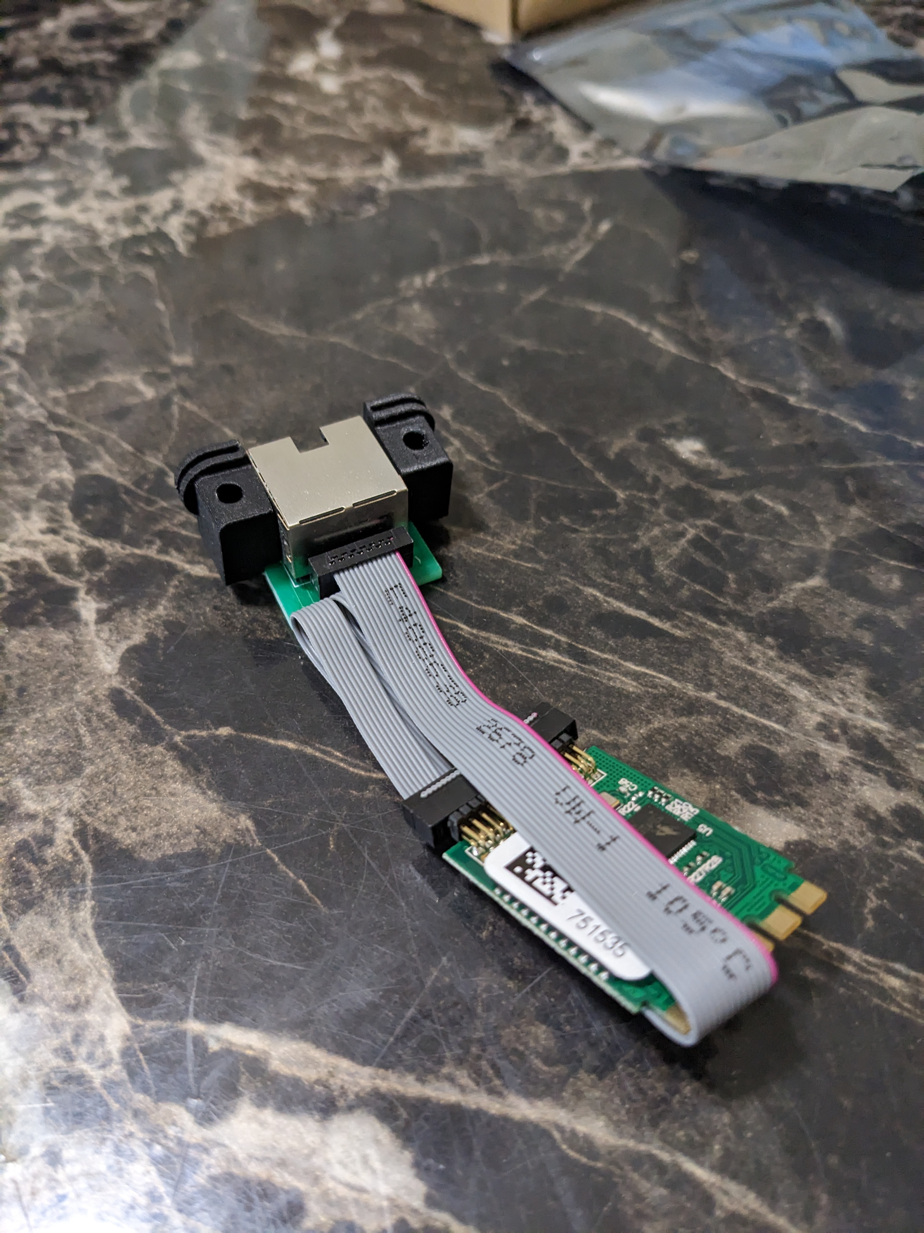
This is what it looks like when the pieces are fit together, for demonstrative purposes only since the pieces will be installed in separate steps.
Step 2
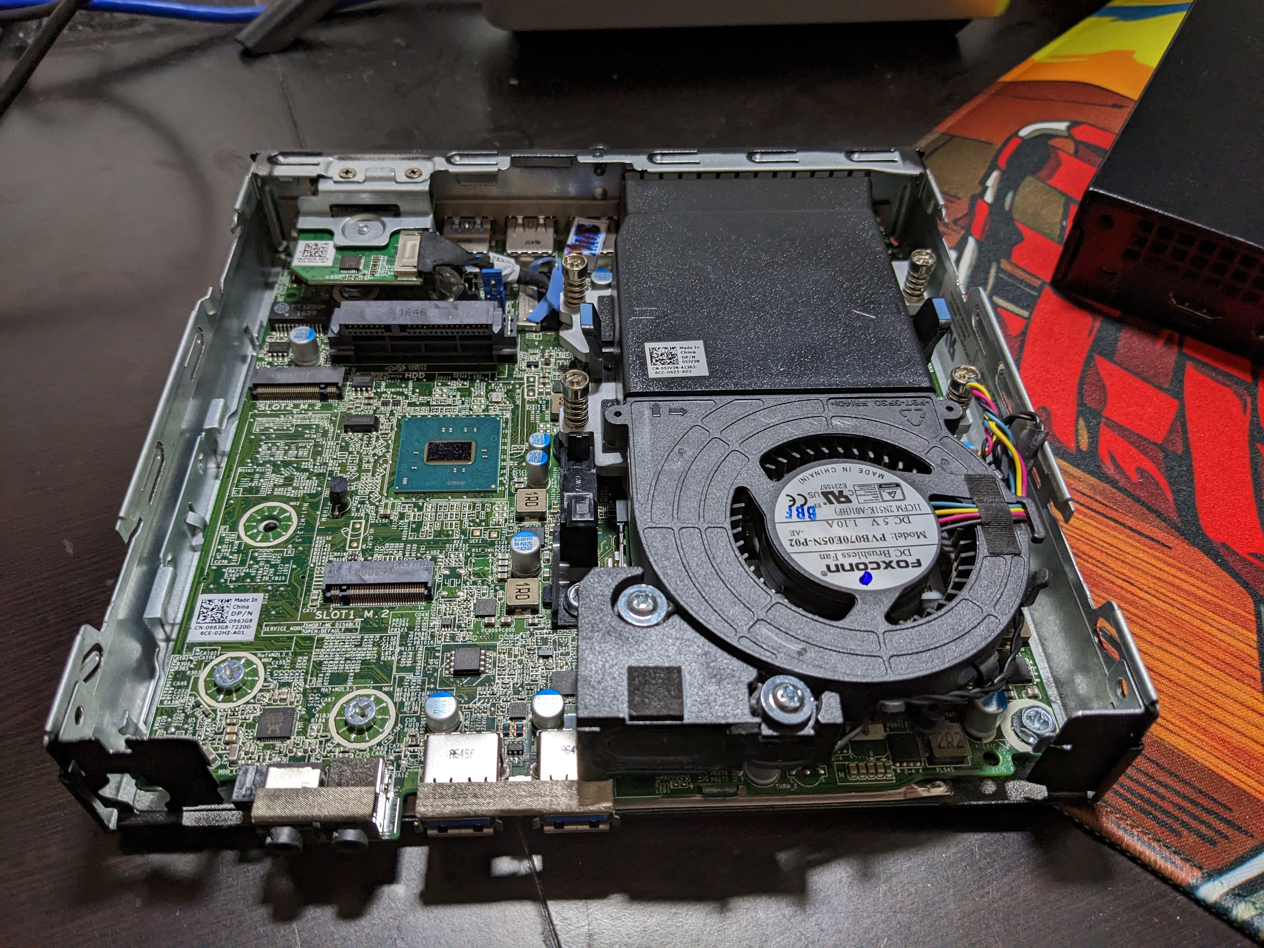
After popping the cover off (unscrew the thumb screw in the back and pull the top cover forward.
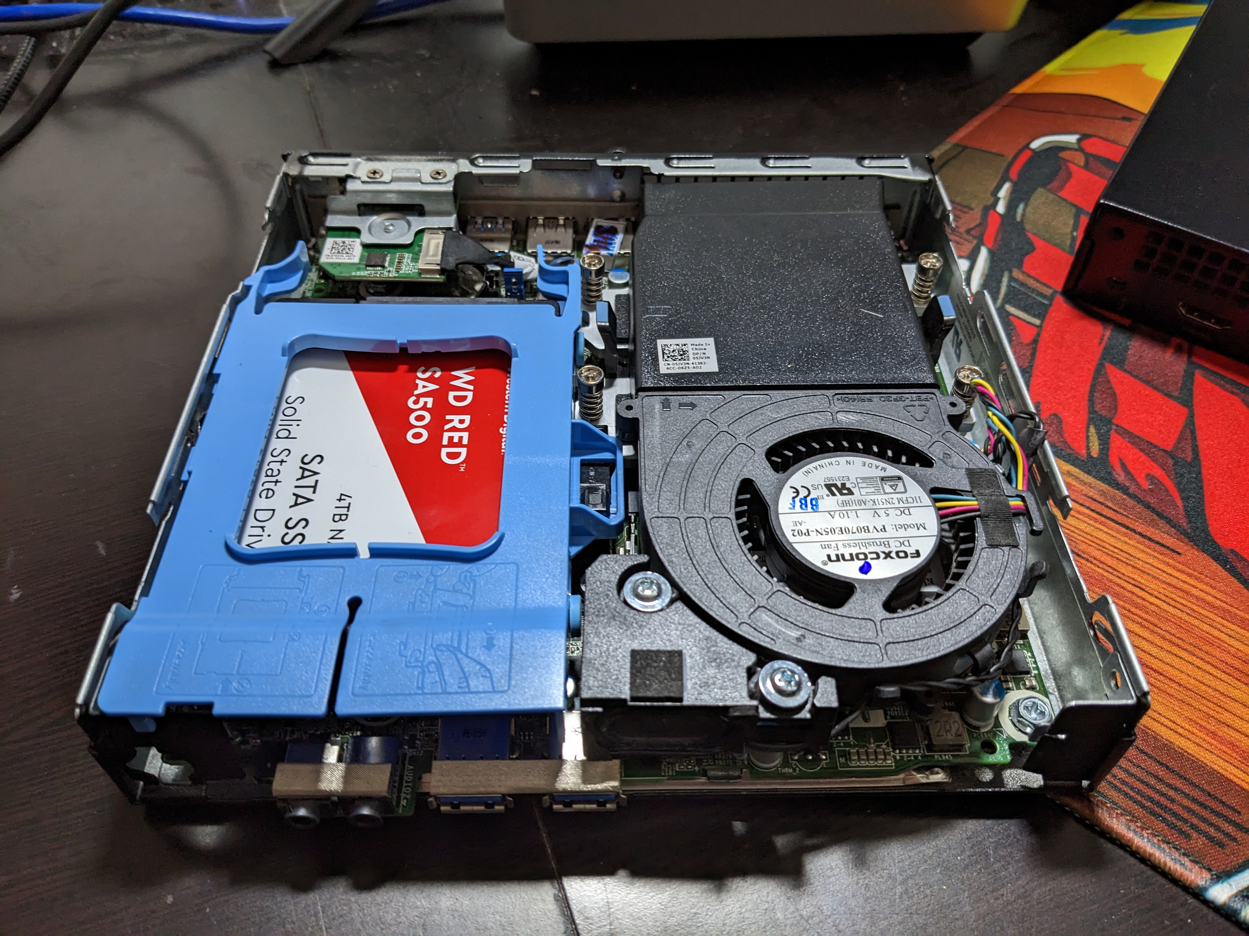
Pinch the blue 2.5" drive caddy at the back and pull it foward to remove it.
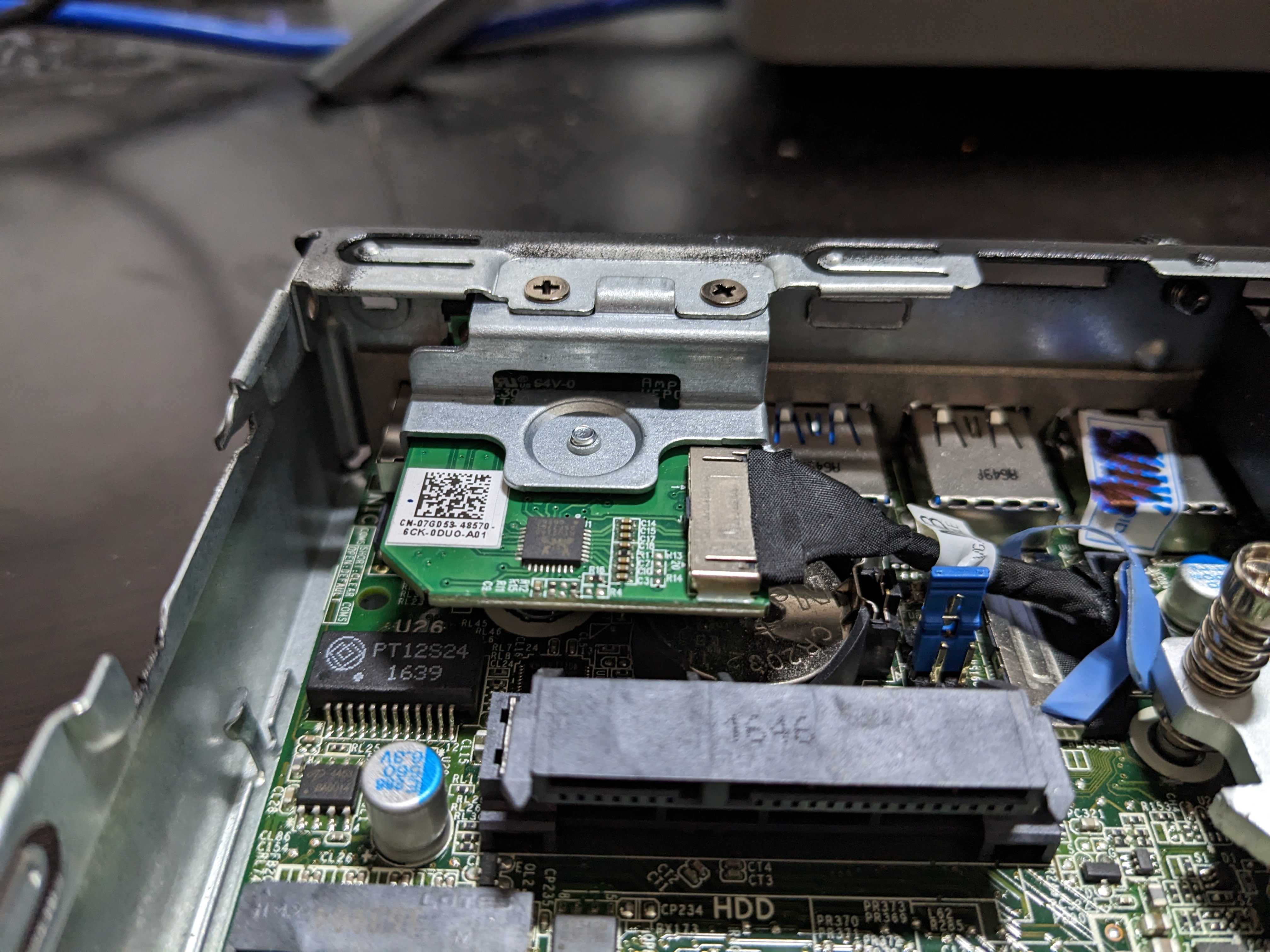
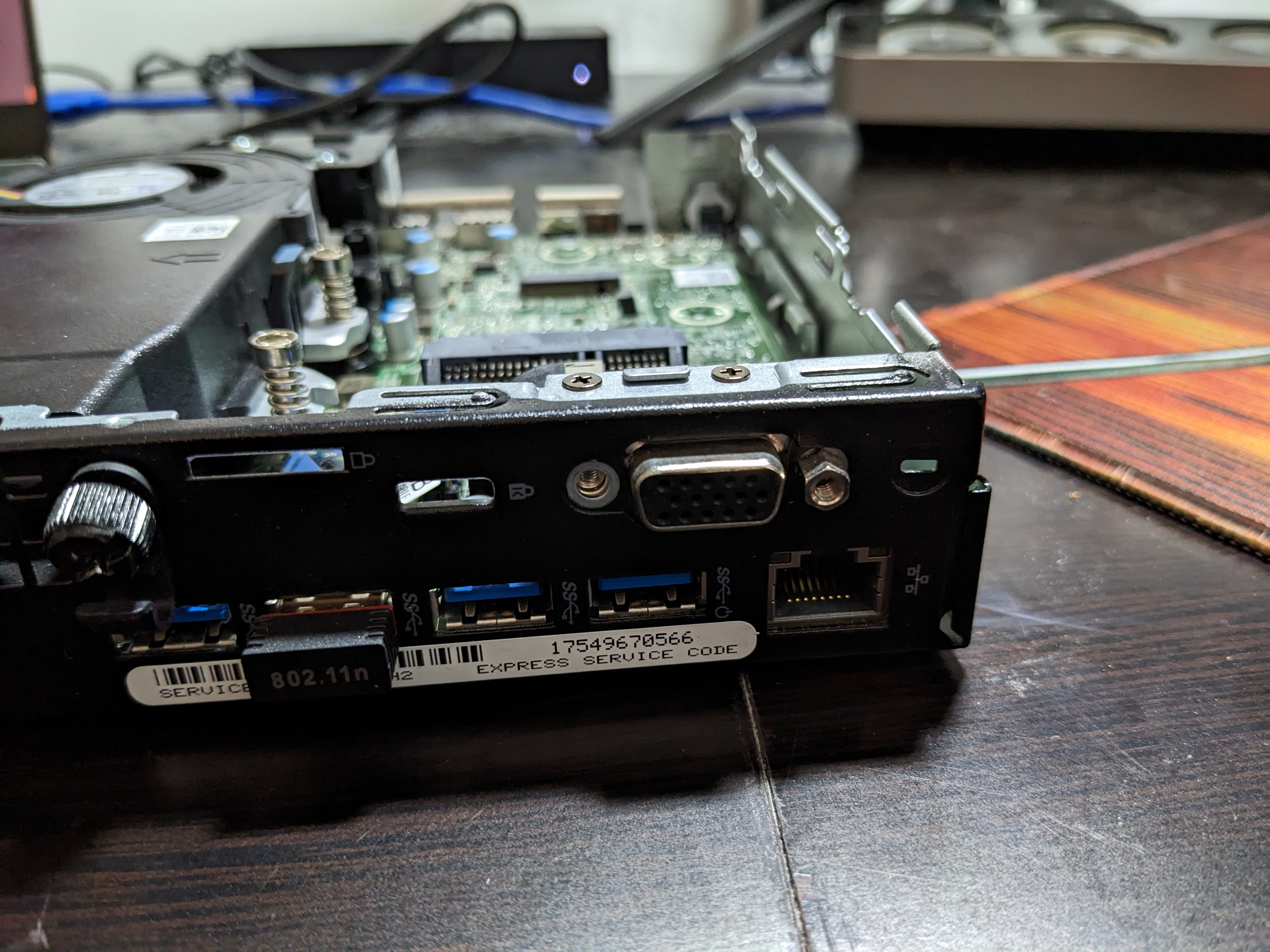
You might have a serial console installed; you'll have to remove this. Unscew the screws.
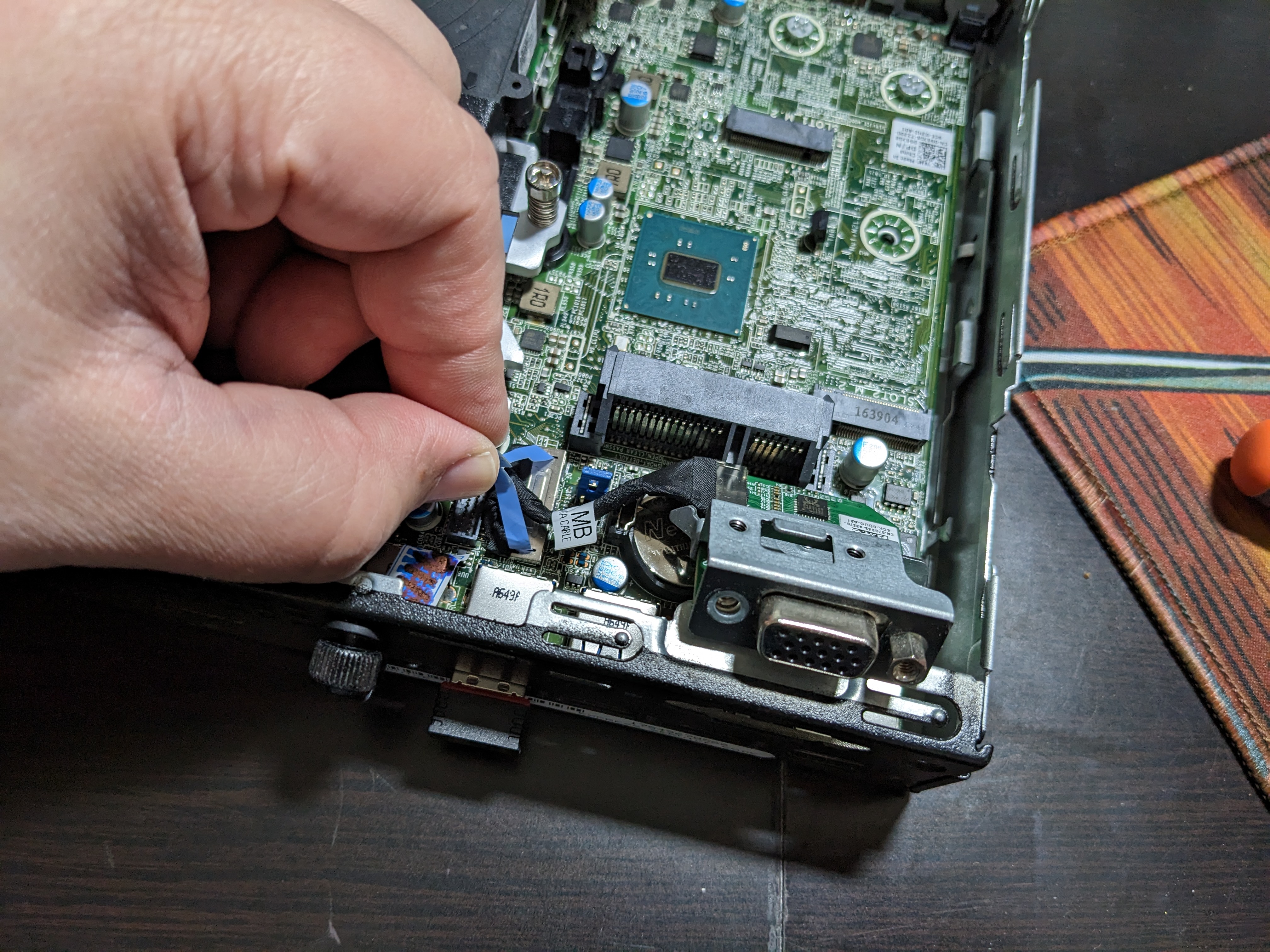
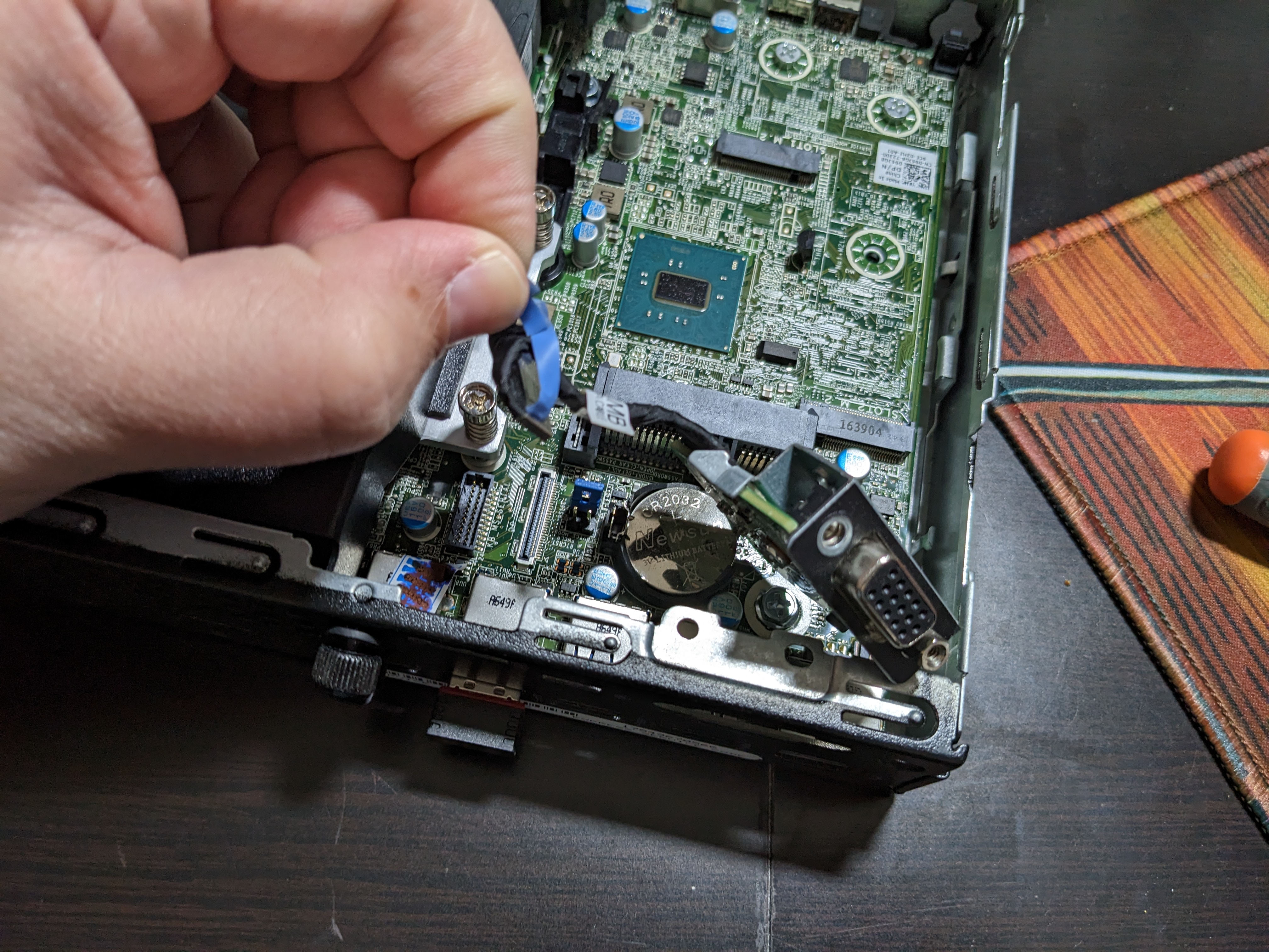
Disconnect the ribbon cable from the motherboard by pulling the plastic piece.
You might also have a piece of metal covering the port, you should be able to stick the Phillips head screwdriver into the plus-shaped hole and just wiggle it up and down gently until it comes off.
If you have a wifi card installed, you must remove it. The card can be unscrewed from the motherboard easily, but it has two wires. One leads to the antenna port on the back, you can unscrew that with an adjustable wrench. The other wire runs across the front of the case and there's a piece that can be unscrewed on the front right side of the computer. Once both are removed you can continue.
Step 3
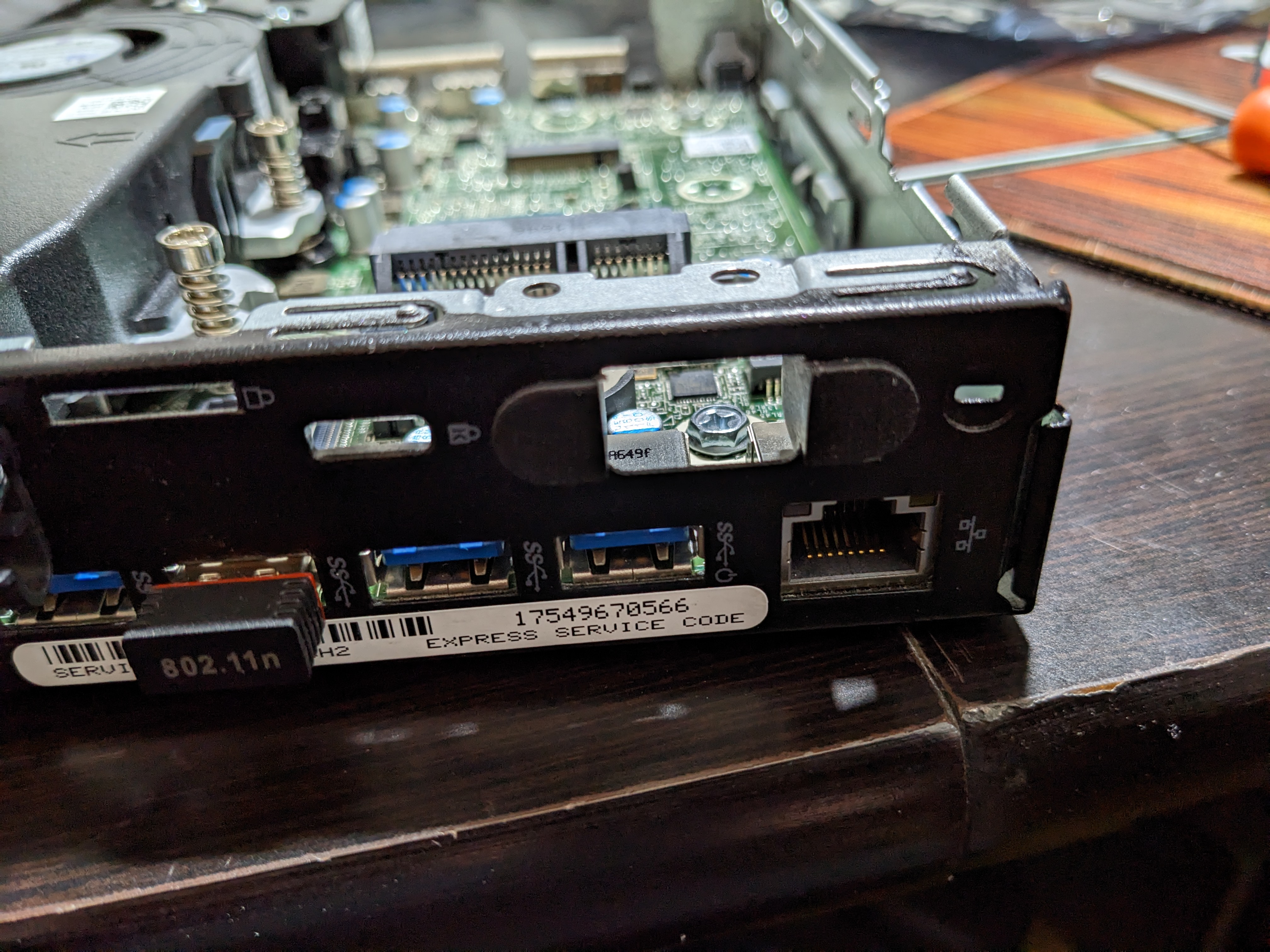
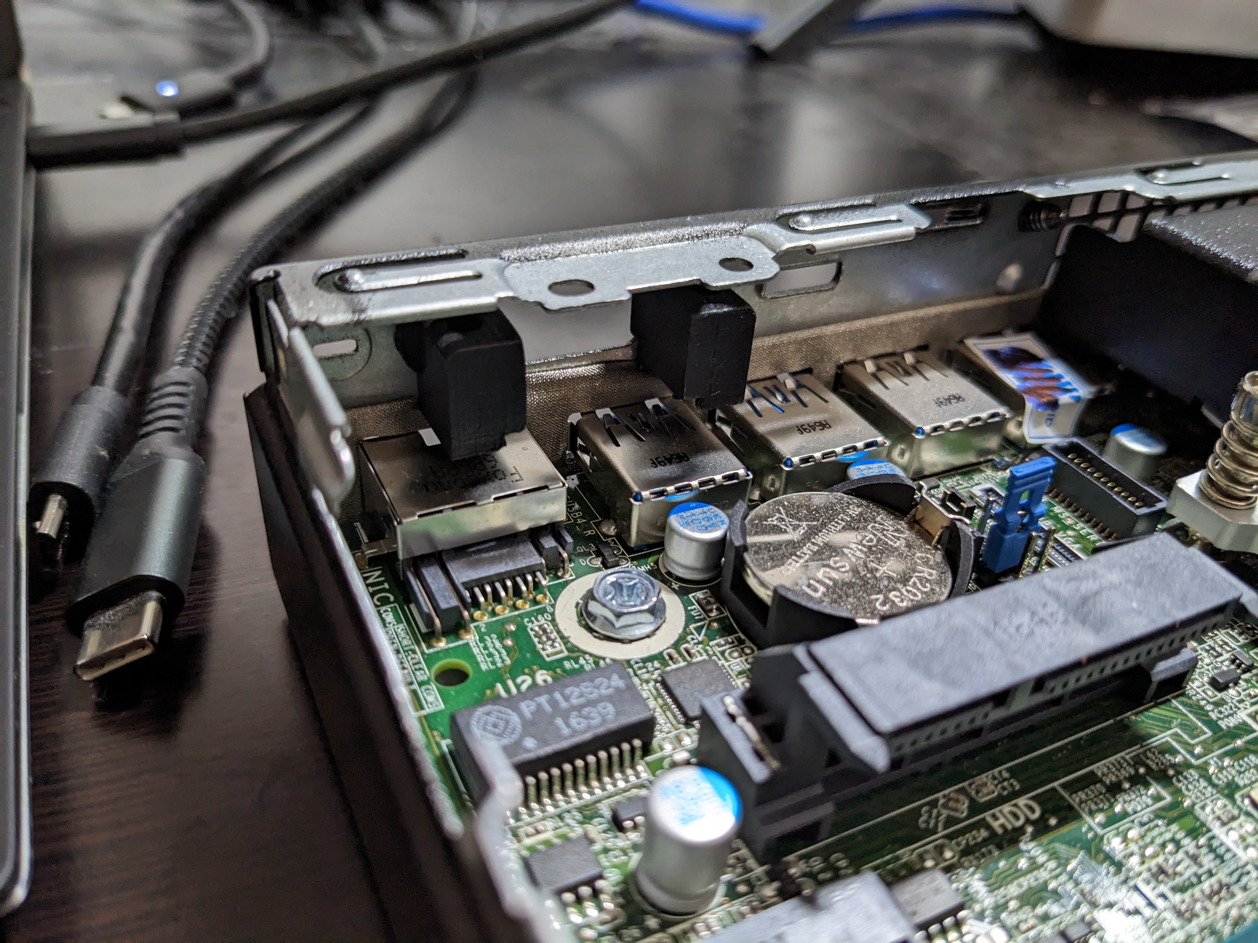
Place the 3D-printed pieces into the port (each can only go in on one side). You can use pliers or stick the screwdriver through and push against the sides to align it.
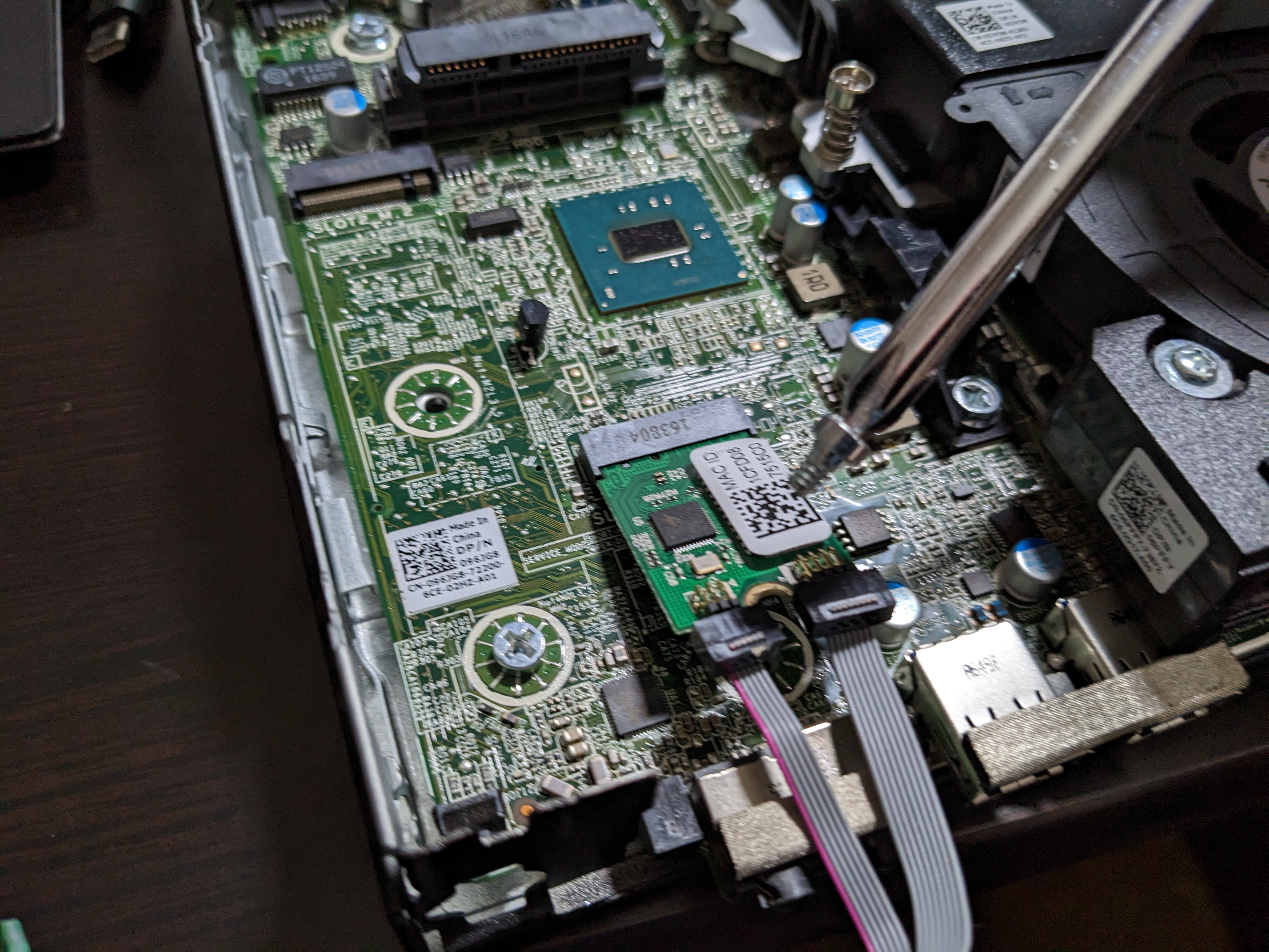
Remove the screw for the PCI slot. Install the card into the PCI slot (It can only go in in one direction). The ribbon cable should turn 90 degrees at the card, run flat upwards until after the SATA port, take a gentle 90 degree turn right and then another gentle turn left.
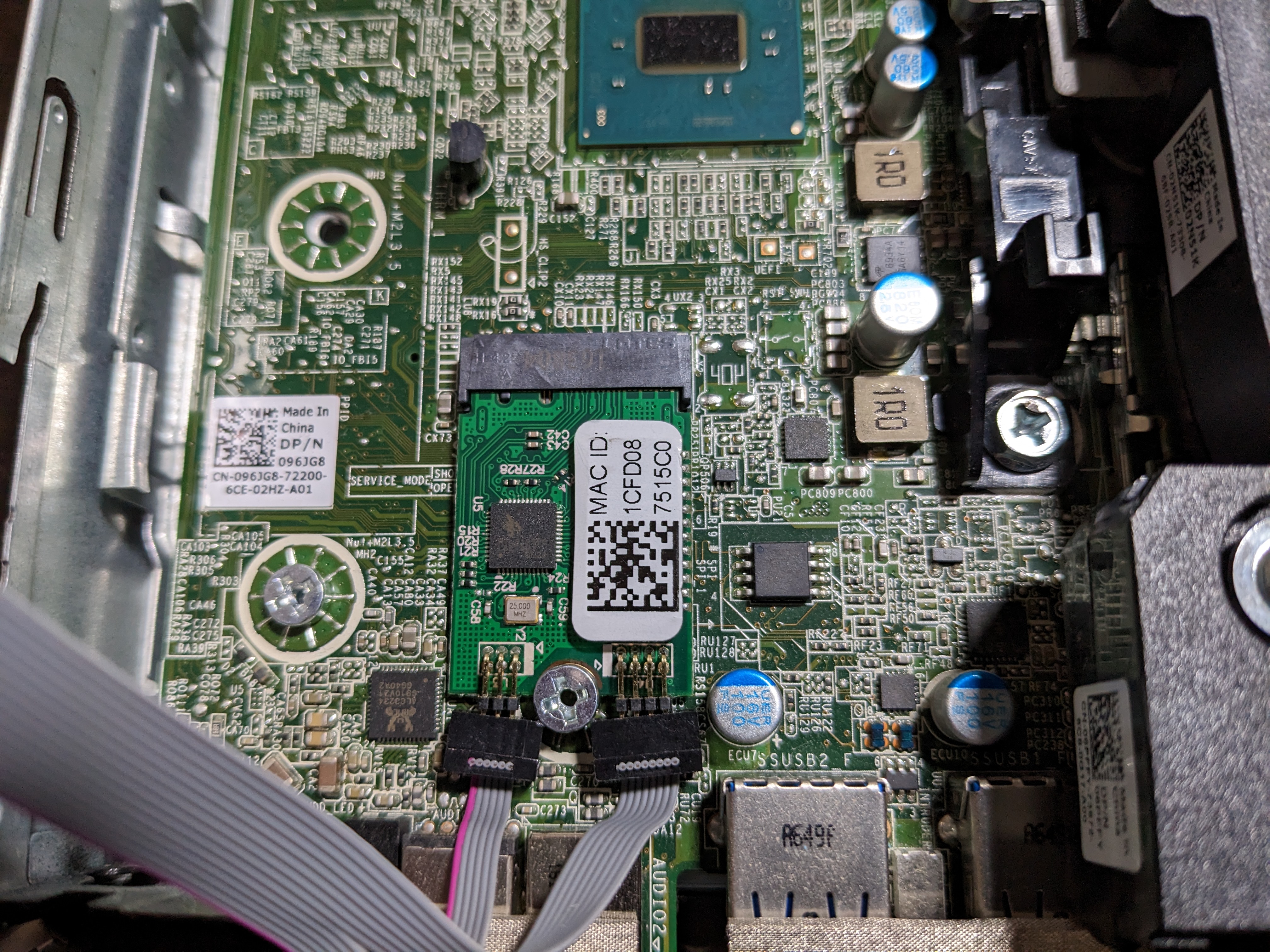
Screw the card down, but don't screw it all the way in, the screw will push the pins slightly. 3 turns after it catches with the motherboard is fine.
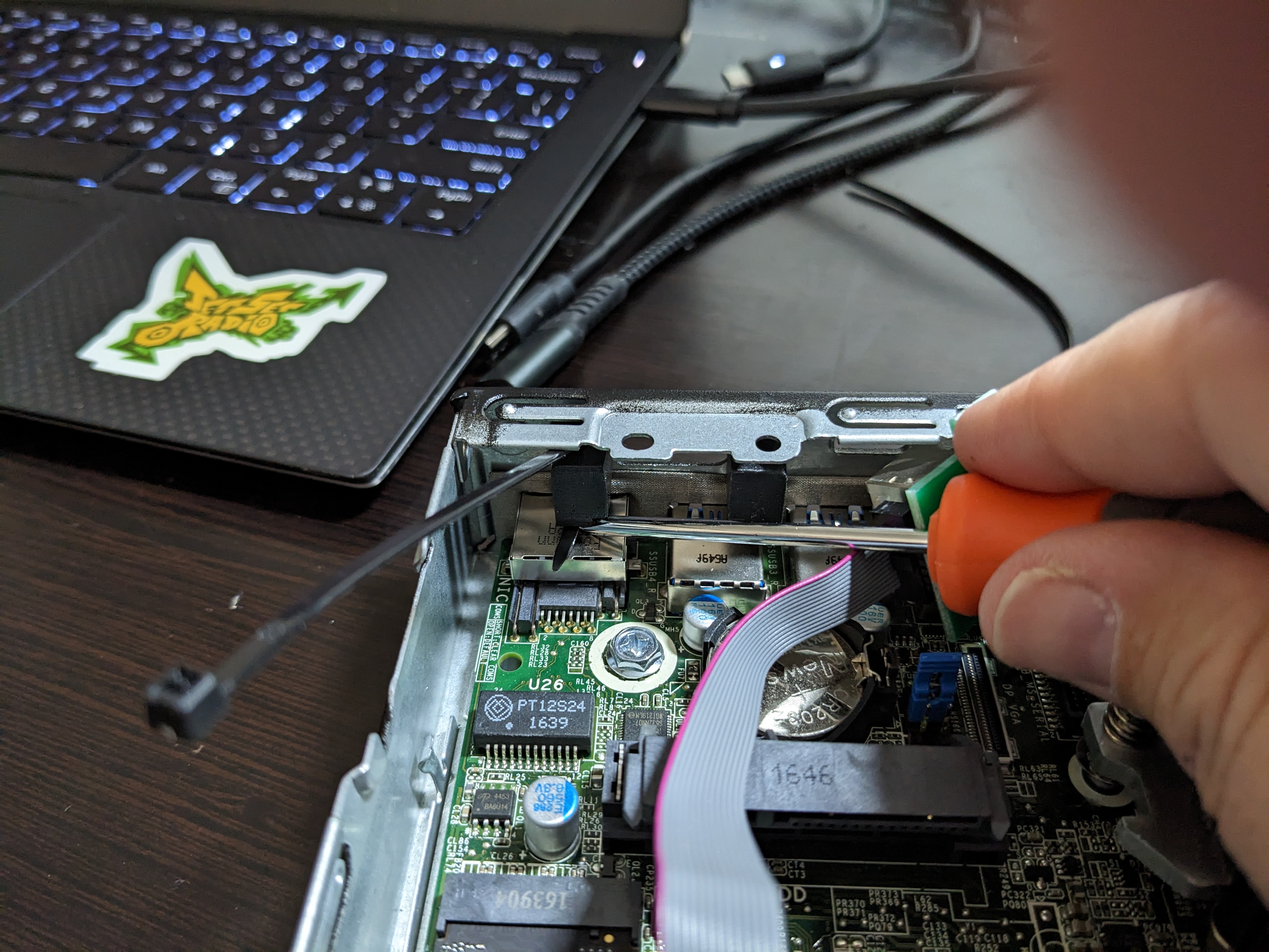
Thread a zip tie through the left mounting piece without the port installed. The flat side of the thick end should be facing you. There isn't a lot of room between the piece and the shield below it, so threading it through now is much easier.
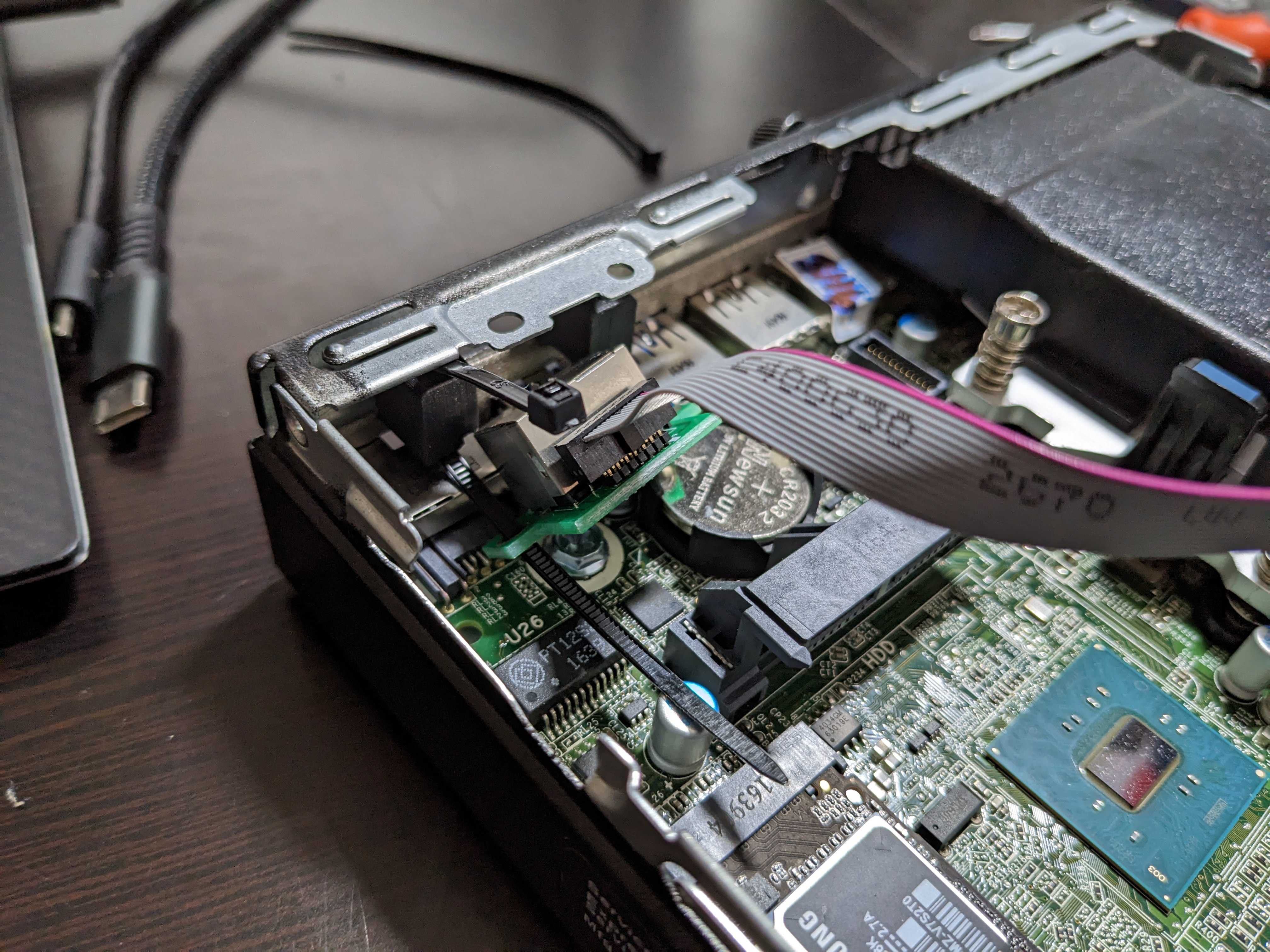
Thread it through the PCB of the RJ45 port.
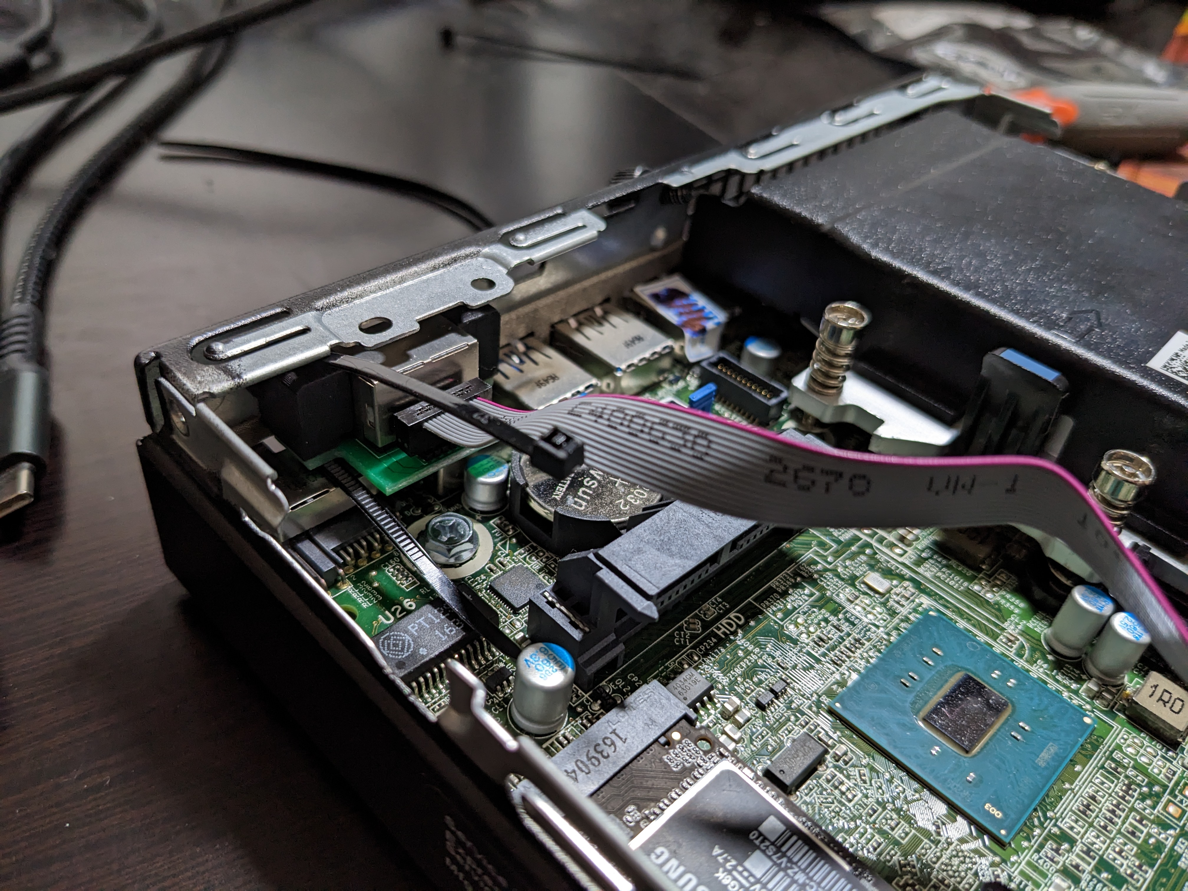
Gently slide the RJ45 port and PCB forward so the zip tie is properly threaded through and it's more or less aligned with the punch-through.
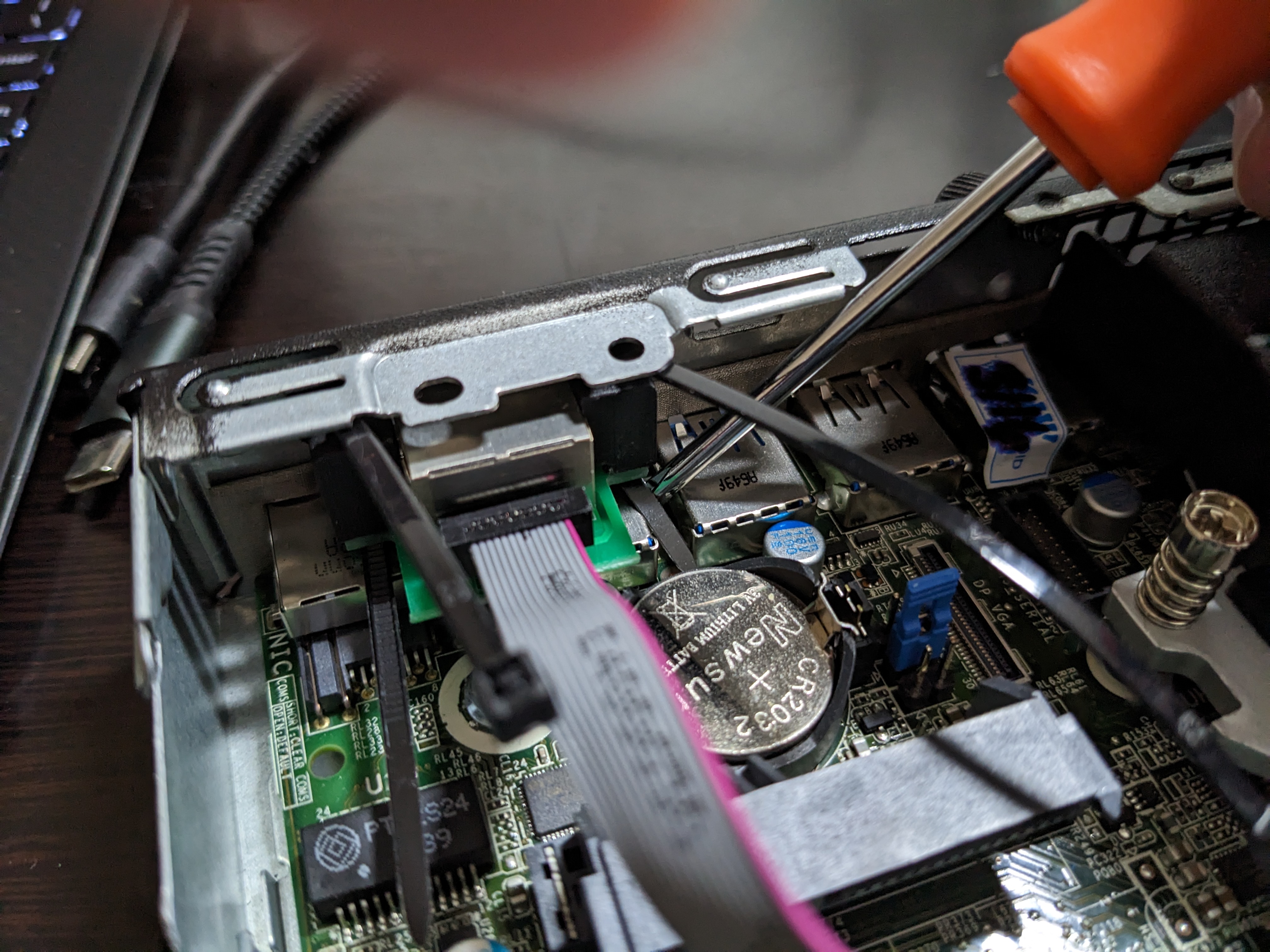
Do the same for the right zip tie, which is a little easier to thread. You can use a thin screwdriver or small pliers to guide the zip tie away from getting caught on the motherboard and to hang free above it.
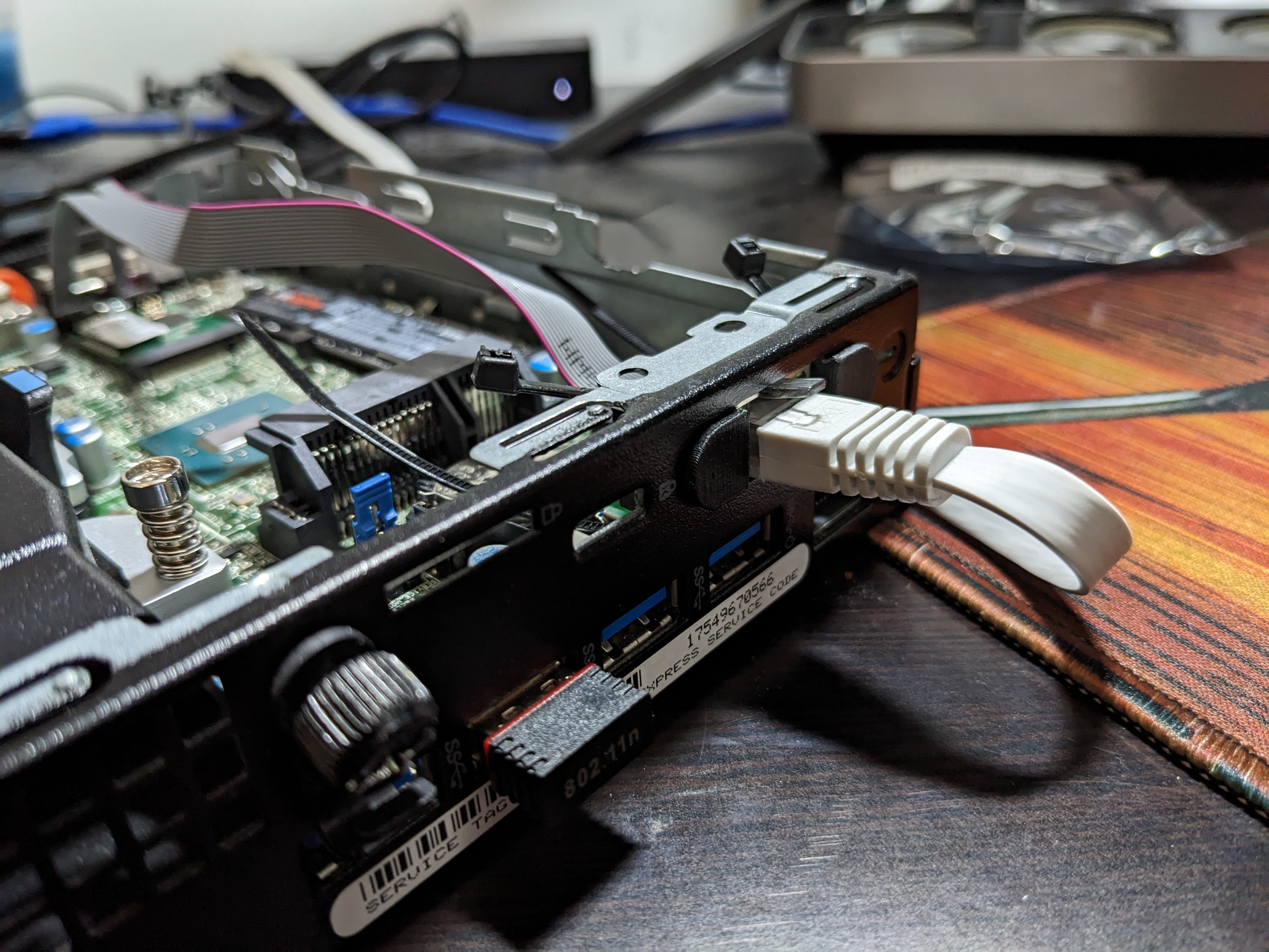
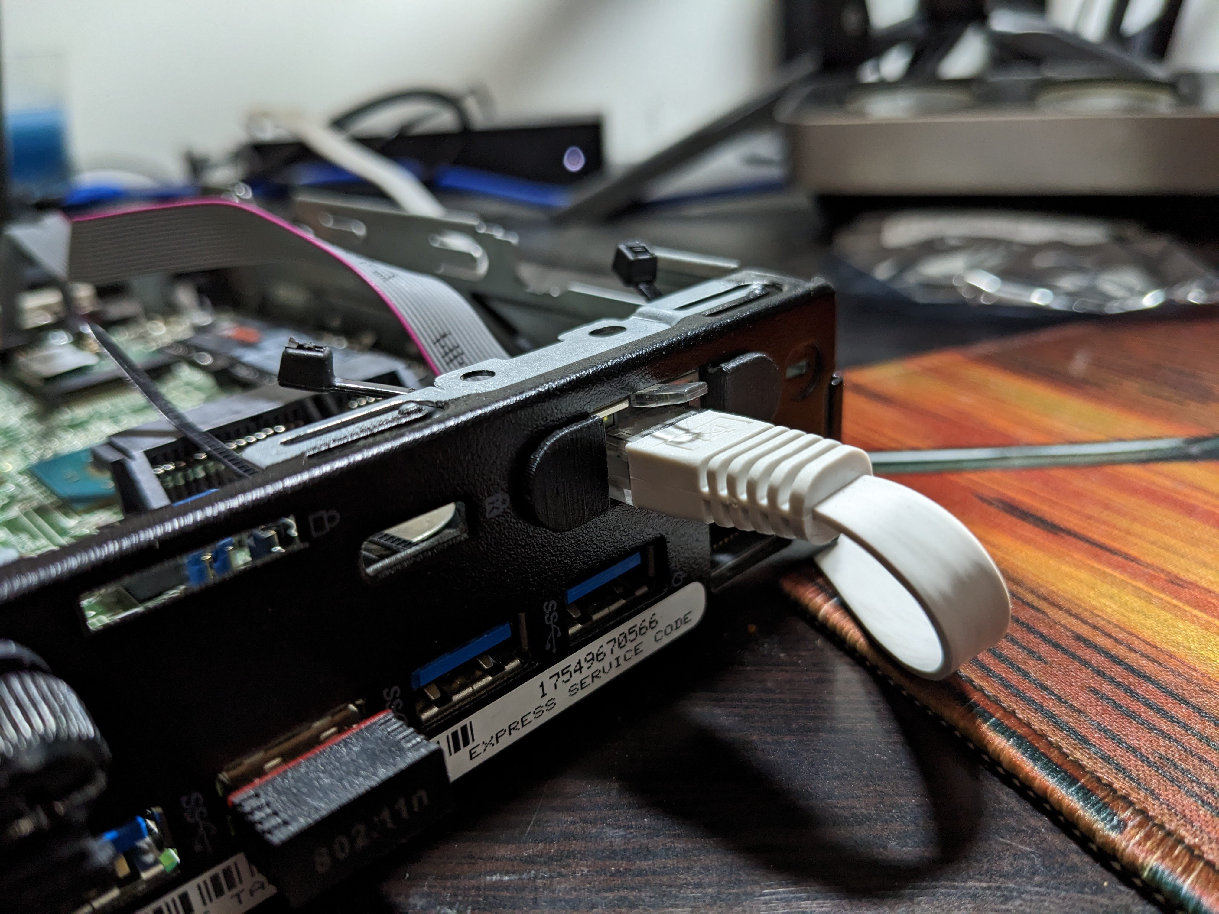
Stick the ethernet cable into the port to help you lift it and push it outward to fit into place with the pieces. If the retention tab has been broken off then it'll be easy to remove especially if unaligned. Otherwise you might be set back a few steps because the circuit board is pushed in and you'll have to redo them. The last picture should show the port is slightly higher than it was before.
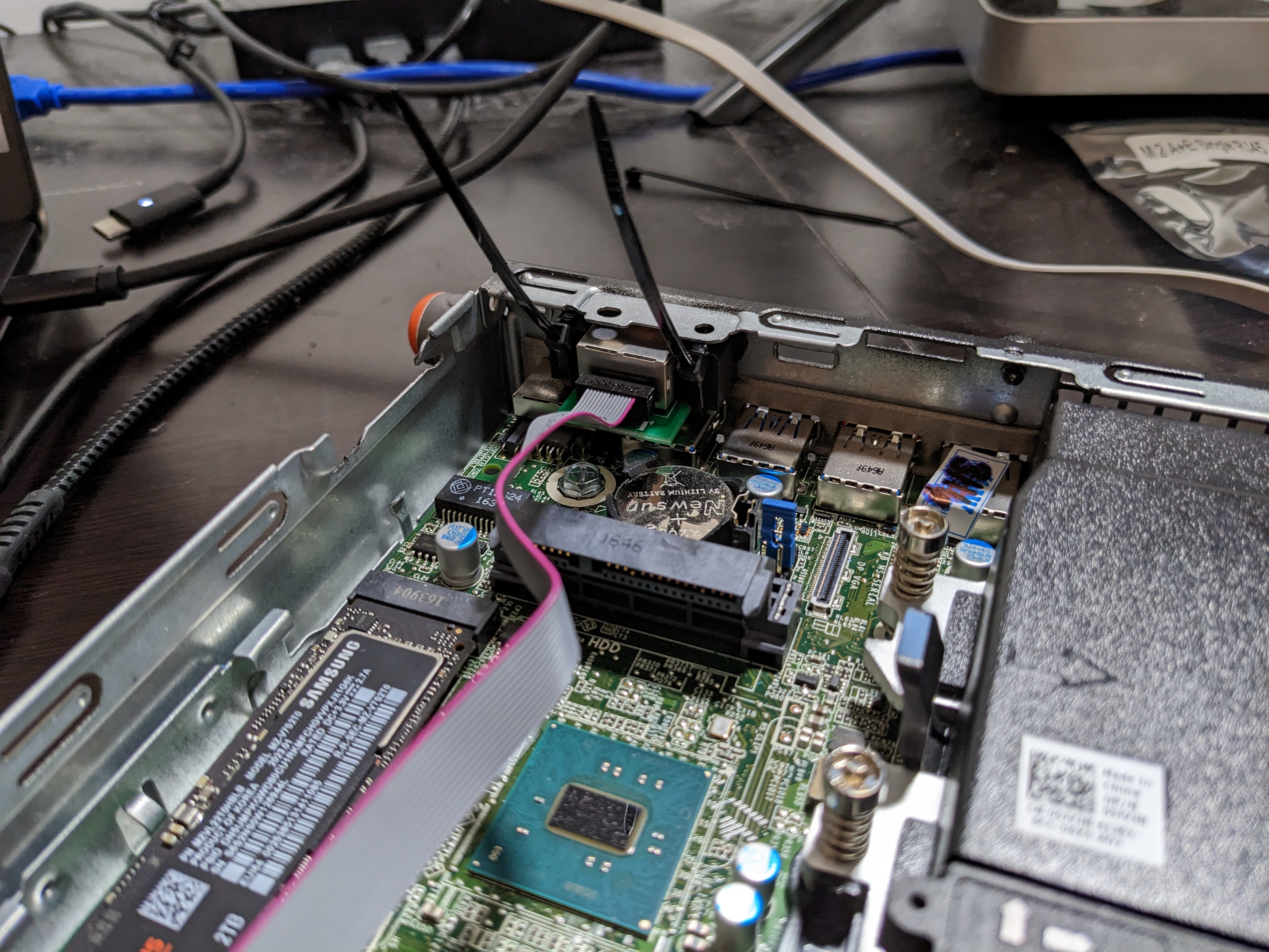
Pull the zip ties tight on both sides. Clip with scissors.
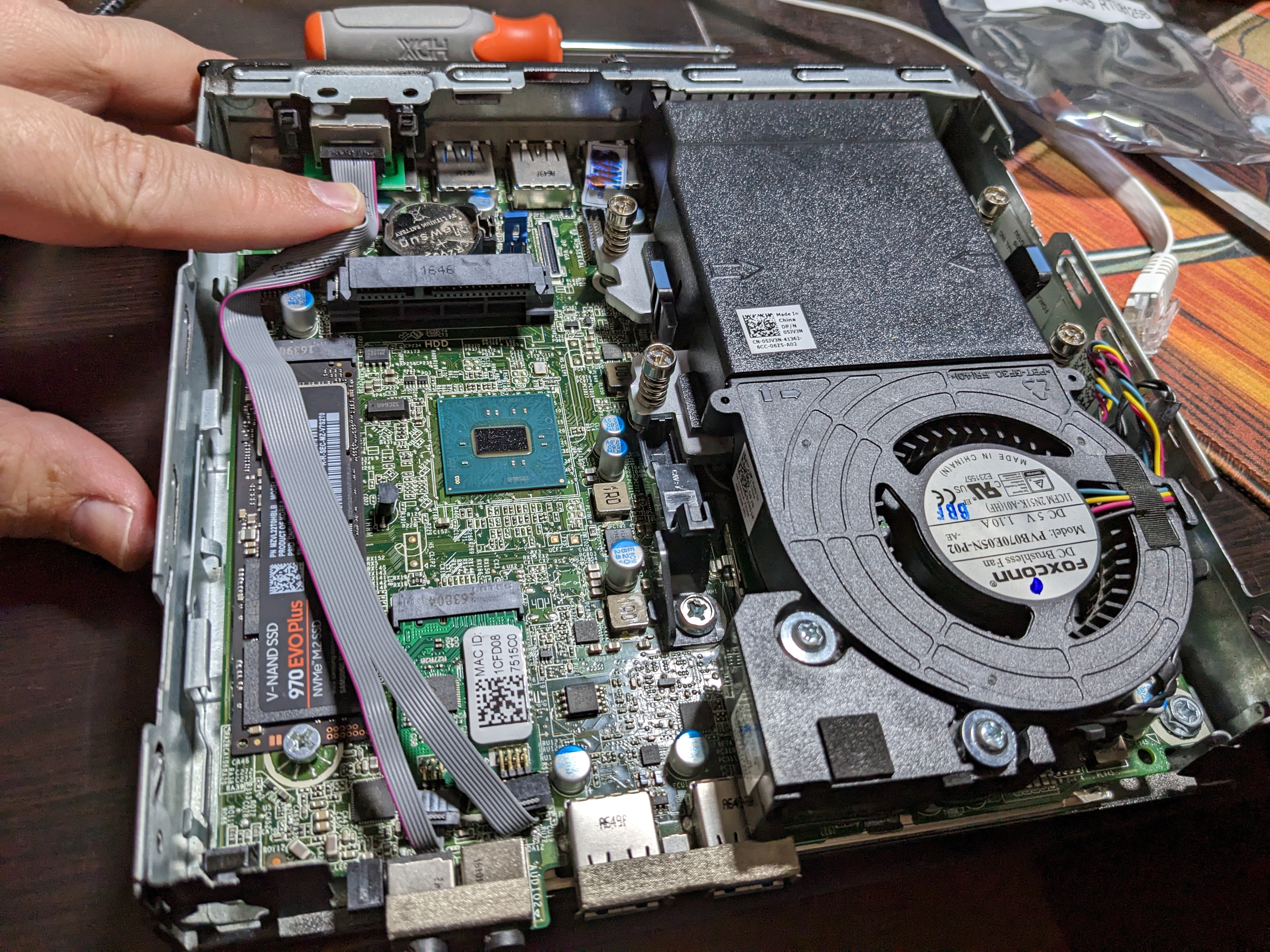
GENTLY bend the ribbon cable so it flips over at the card, does a 90 degree turn right after the SATA port and then gently bends back.
Step 4
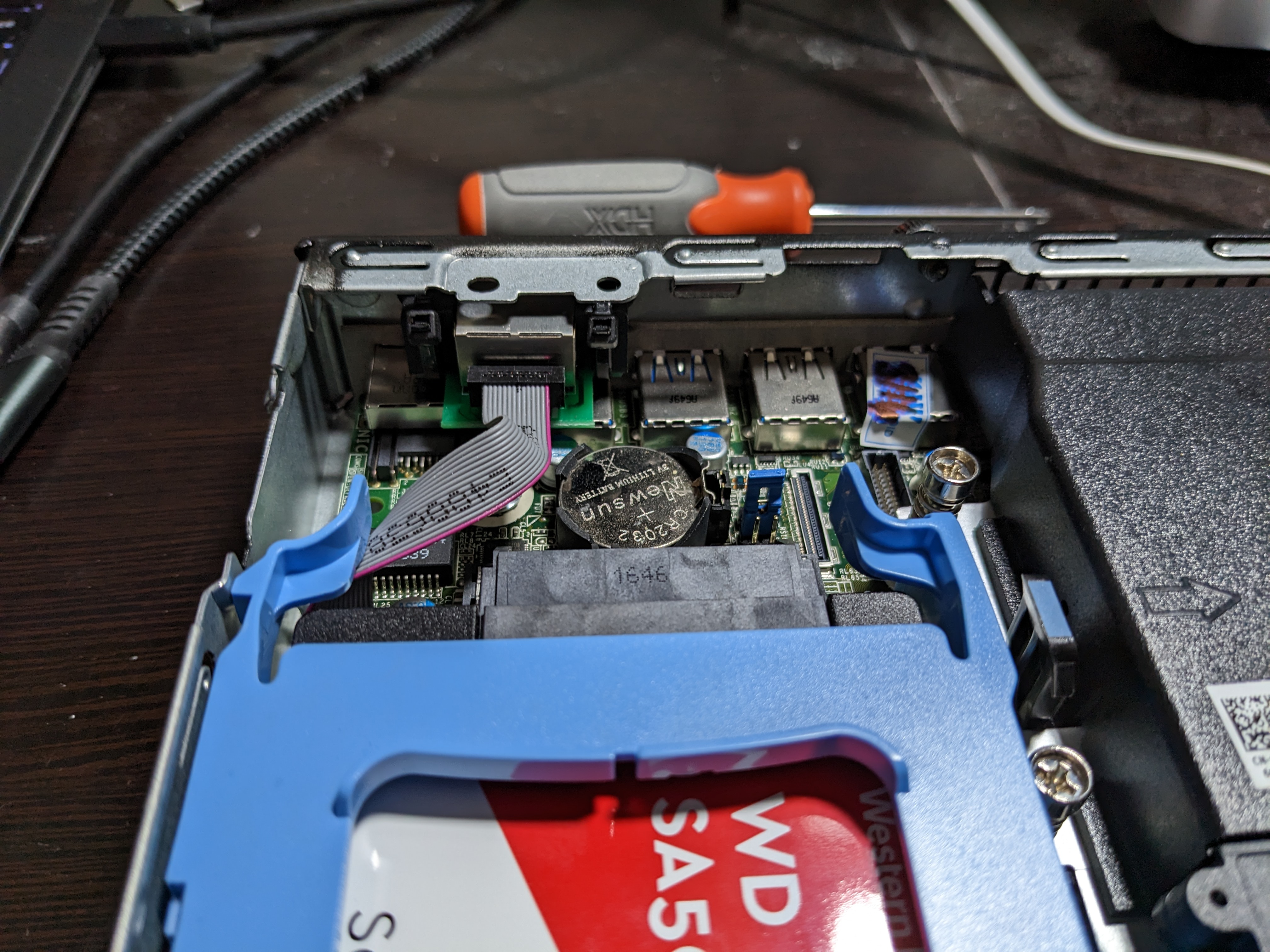
Place the 2.5" caddy back into place, careful not to pinch the cable anywhere.
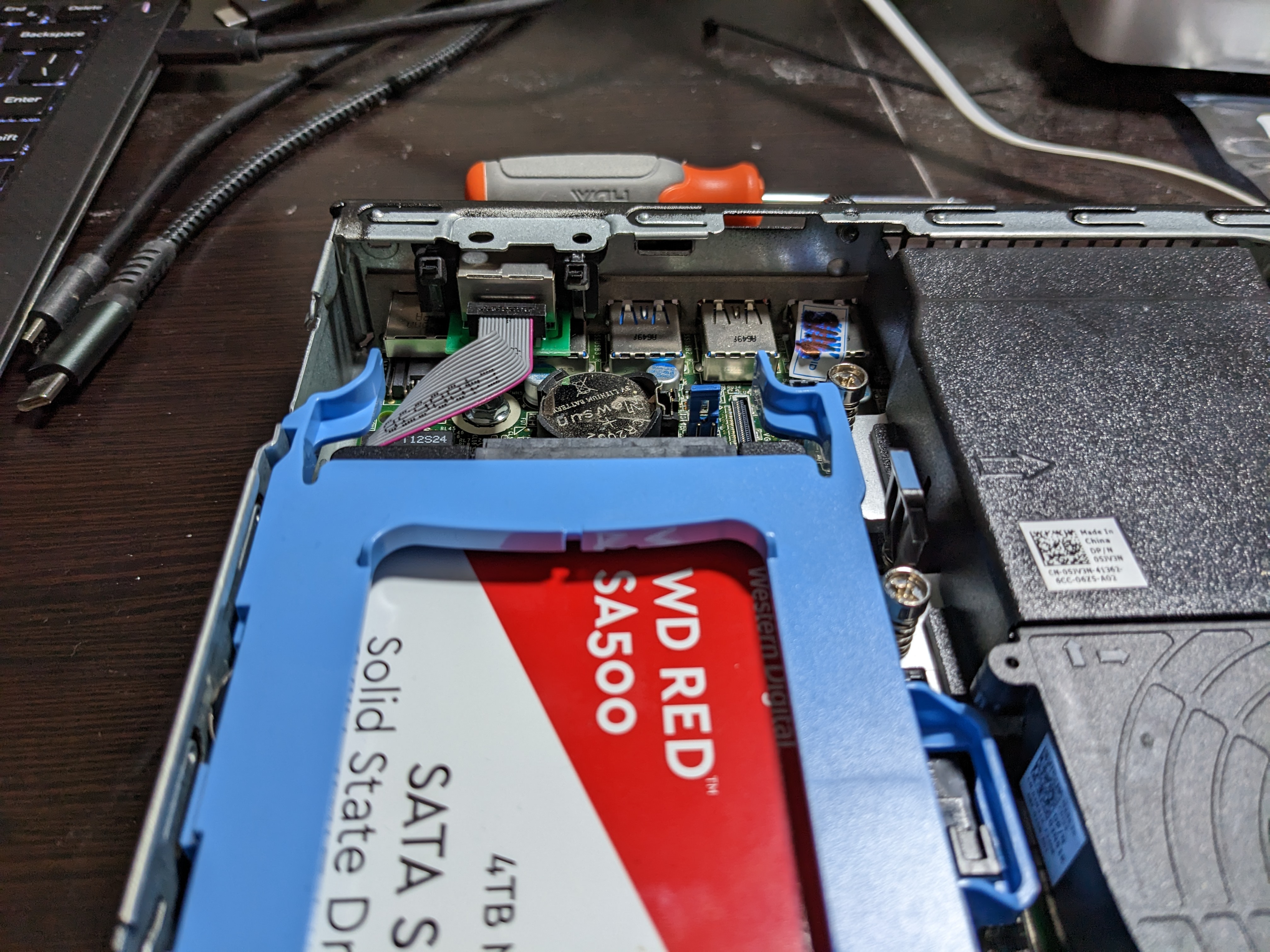
Slide it back into place, the ribbon cable should not get caught, but run between the 2.5" SATA assembly and the motherboard/NVMe drive.
Step 5
If your system had secure boot, your system will prompt you to complete these steps. Otherwise, this will be a normal boot and you're ready to go!
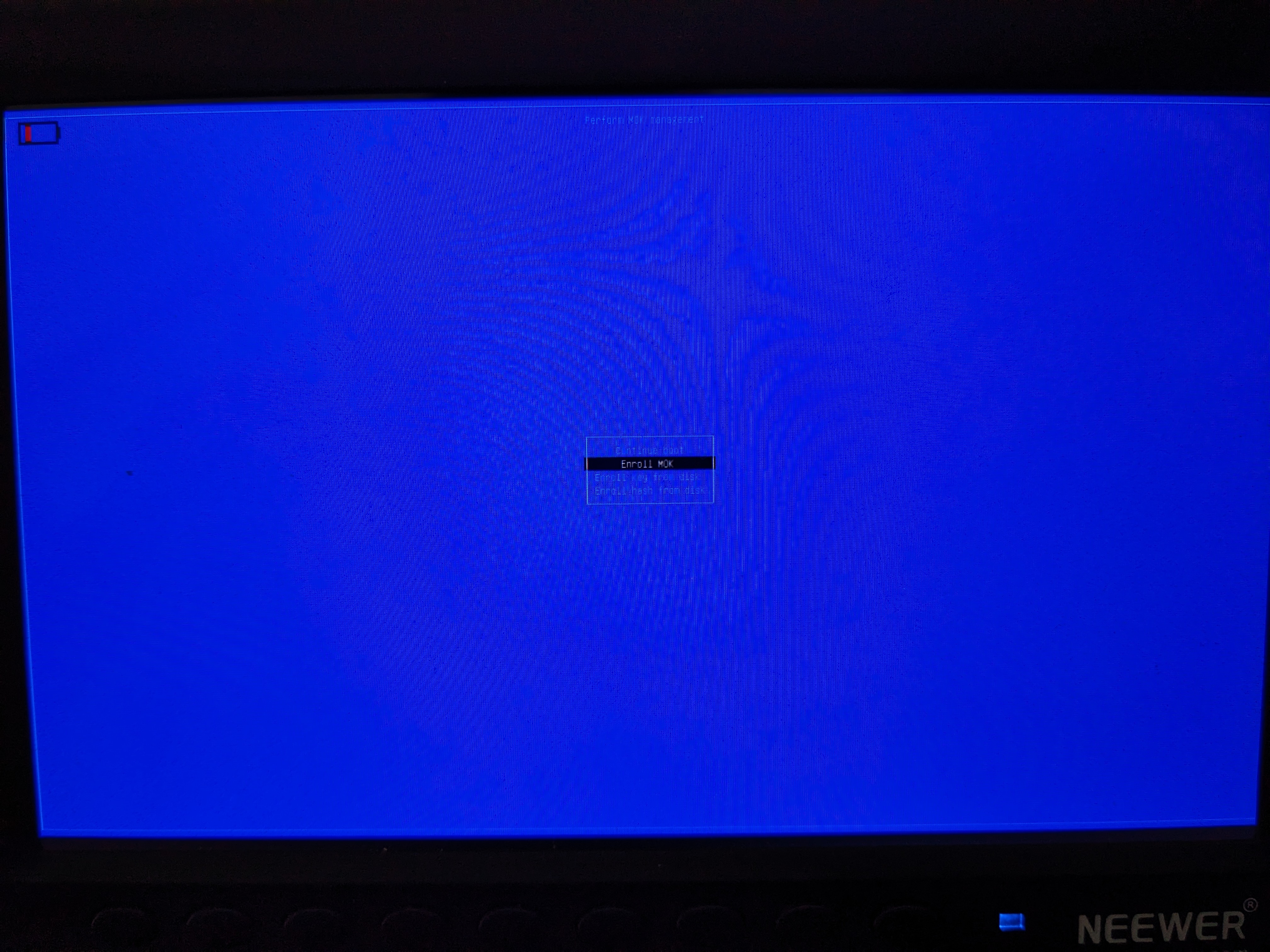
Select the second option, "Enroll MOK"
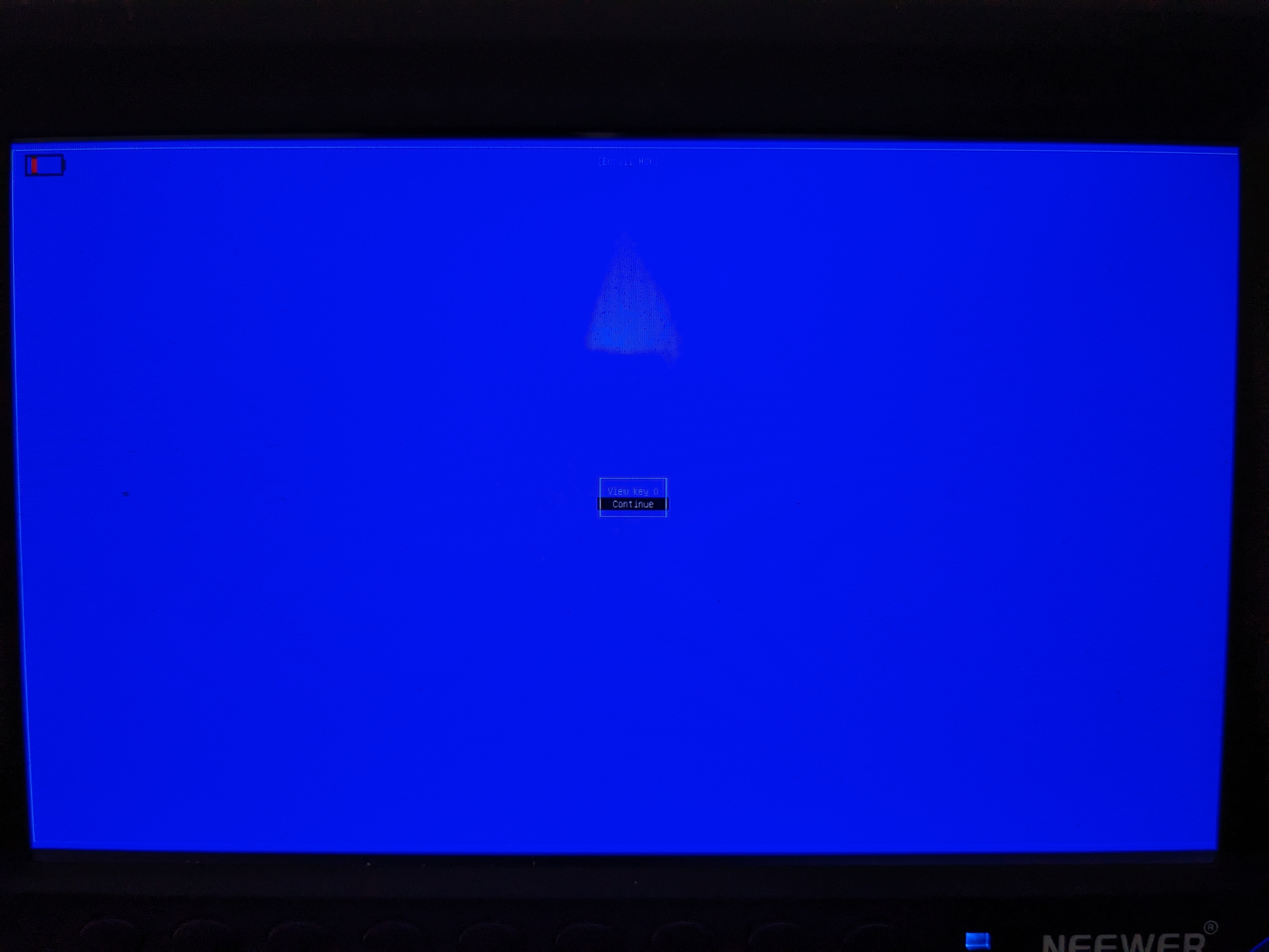
Select Continue.
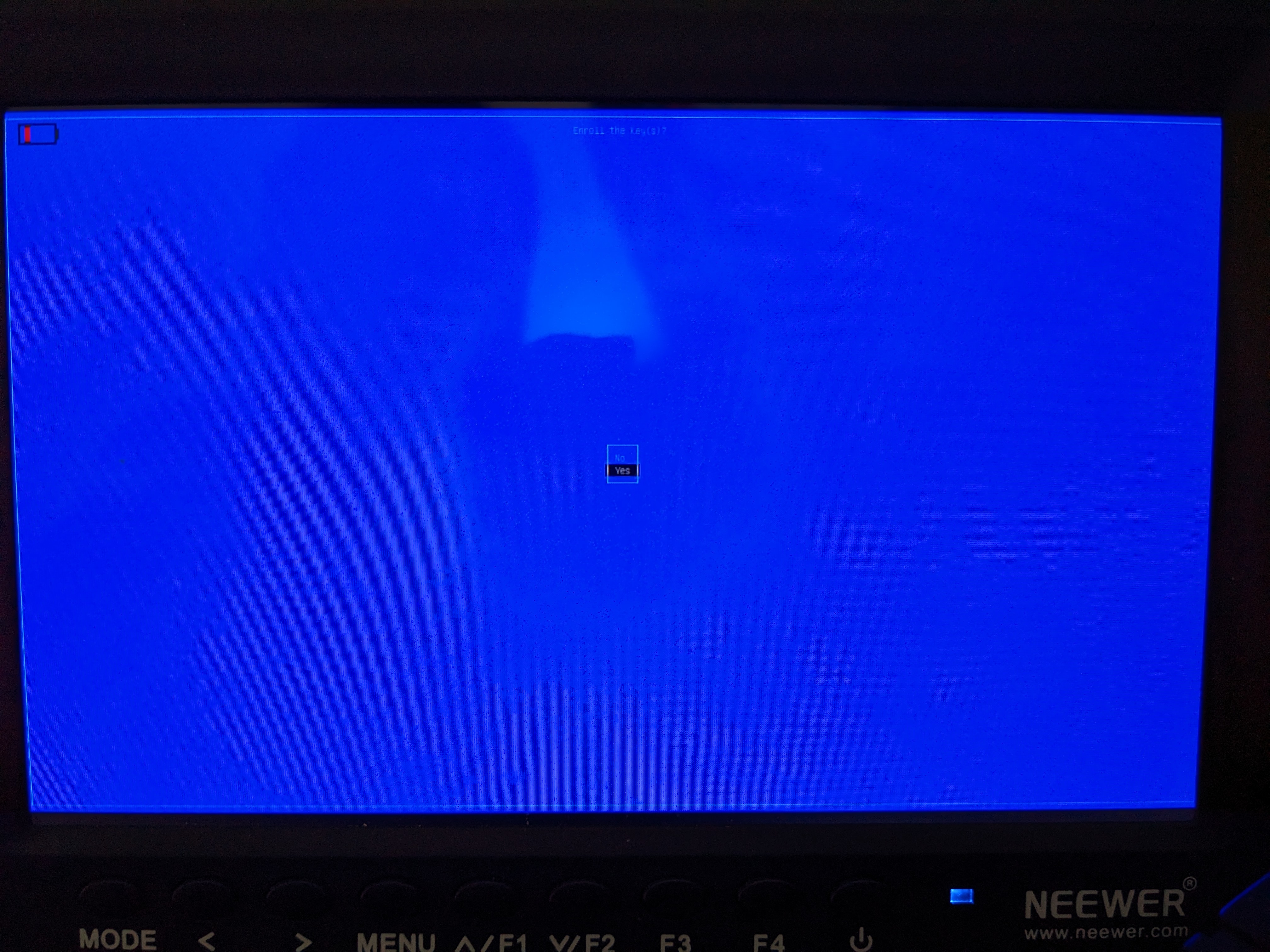
Select Yes.
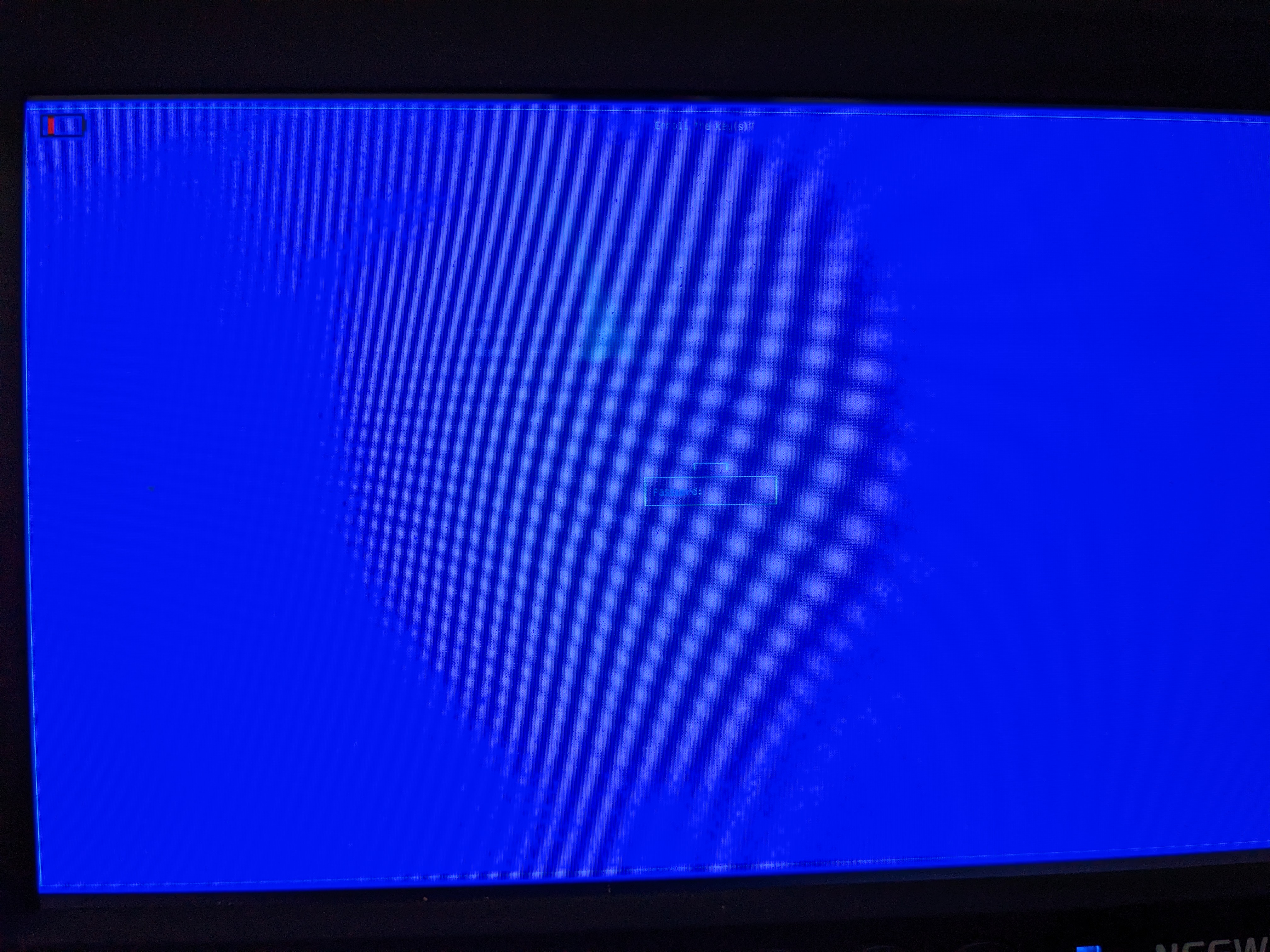
Enter your password you came up with earlier.
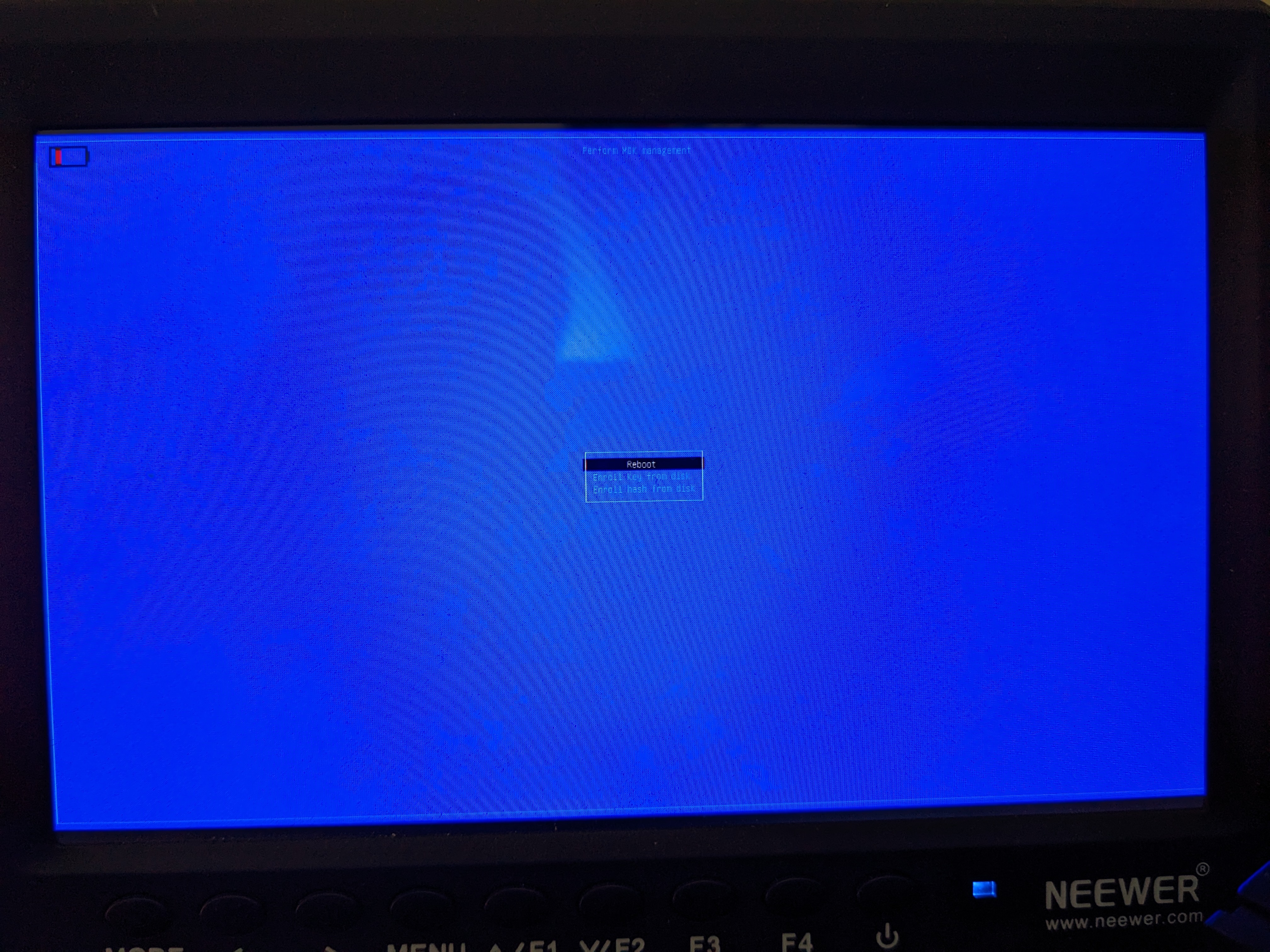
It won't display any message indicating success, but if you see this, it was. Reboot and you're good to go!

